18 x 33 x 56" Semi-In Ground NJ

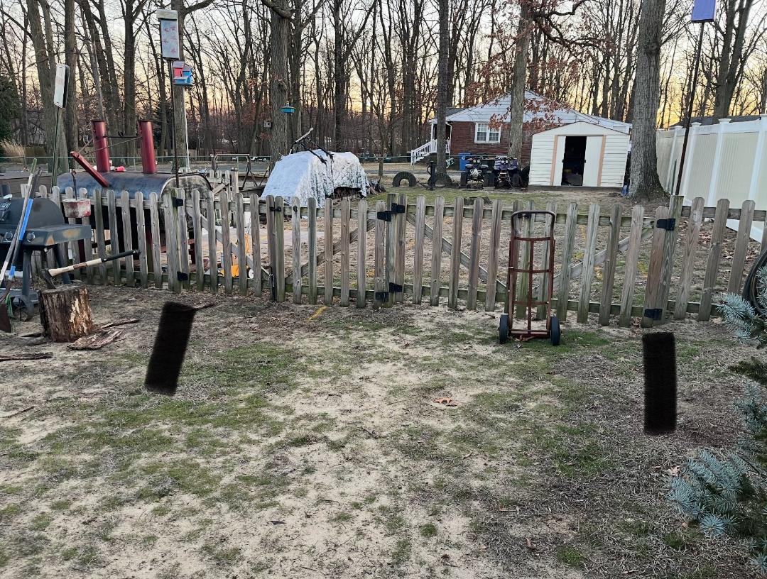
Alrighty so I didn't quite make my plumbing list last night since I was fooling around with layouts on the plumbing. Originally, I had everything at the back of the yard but then I realized I would have to do all of that after pool construction since the gate (in between the black lines) is getting removed to allow access for excavation and so on. A solid fence is being built in place of the gates, pickets will be added as well to eliminate any footholds on the fence, and it is already above the minimum height of 42".

F/P are the Filter and pump assemblies, The equipment pad is 3' x 5' in the plan but I think I may go 3x6 and will more than likely make a hinged roof off the fence to keep the sun off the equipment; more on that when I get to it 😁.

Anyway, plumbing thoughts; as usual, add anything you think would be beneficial to do now
  • All 2" plumbing, the skimmers say 1.5" but I believe you can get a 2" coupler on the outside of them, will verify the skimmer/return models with the pool peeps
  • Unions at the pump and filter intake/discharge
  • 3-way valves after the unions
  • 2" tee's going to returns and skimmers
  • 4- flow valves after the tee's to allow for adjustment
  • Runs to returns/skimmers 12" below grade
  • Unions
  • Shutoff valves below returns and skimmers

    • I may put and extra Tee and valve in the "top" return line (looking at the picture) for a fountain/water feature to help cool in summer
    • I may also put in a bypass for a WOOD FIRED HEATER down the line, I am holding my ground on not getting an electric or gas heater 🤣😂🤣😂🤣😂 my PSE&GH bills are high enough and I'm sure they will be more with just the pump lmao.

*The red and yellow are electrical before anyone asks lol, outlets at the patio will probably come next year when we do everything else.


Pool Plan 1.pngPool Plumbing .png
Gate 1.jpg

Gate 1.jpg

Pool Plumbing .png

Pool Plan 1.png

Draining Above Ground Pool - Questions

As a AG pool owner who had a winter cover split during the winter many years ago I want you to think about not doing this if your pool doesn't have a bunch of debris sitting on the floor.

If it's just green and yucky,, chlorine will clear it up. Yes you need a lot but it will go from dark green to light green quickly. I don't know what kind of filter you have but if it's a sand filter get some diatomaceous earth (DE) to get it to filter finer. I had a DE filter then and it cleared the water up fast. It will need to be backwashed often though because of the fine filtering. You could start it on recirculate to get the chlorine moving. Once the water is clearer and you can see what you're up against you can start brushing the sides and floor of the pool. I can't say what to do if you have a cartridge filter, your way may be better.

It won't be a 1 day job but you'll be keeping the water in the pool so no issues with the liner. I will say that I have not had to use DE in my sand filter yet so I can't say it will need backwashing in a minute, an hour or how long but you'll need to monitor it.

Back then I used bleach not liquid chlorine and I did go through a lot of 1 gallon jugs (10 - 15) and I think it took a week to get the water clear being filtered with the DE filter. It's early in the year and not close to opening, at least in NJ, so plenty of time to get it ready for the new season.
  • Like
Reactions: hvstle

New Hot Tub Owner - Taylor Test Kit

UPDATE:
OK - feeling positive for the first time as I geek out with my chemistry set, here.
To recap, I added 7.5g Dichlor last night as per the app.

Today, FC measured at 5ppm. Combined took 1 drop so .5ppm (using the 10mL water sample).
The buzz is seeing the CYA come up. I filled the TT up to the 30 mL mark and could 'just' see the black dot (holding at waist level). My guess is 5mL more would have obscured it, so maybe 25 as an estimate.

In the app, I just left the CYA field blank. The recommendation is 2.2g of Dichlor.... off to add that now.
Is it weird to get excited about this?

1740721378540.png

Brand New Max e Therm burning through igniters literally

HSI checkout

Check cold resistance
HSI manufactured by Coorstek (KIT03033 pre Sept 2021) resistance range = 40-80Ω @ 75°F
HSI manufactured by SCP (KIT03033USA Sept 2021-current) resistance range = 65-120Ω @ 75°F
Check amperage of HSI when energized
HSI manufactured by Coorstek (KIT03033 pre Sept 2021) range = 3.5 - 3.9A @ 132vac
HSI manufactured by SCP (KIT03033USA Sept 2021-current) range = 3.3 - 3.7A @ 116vac.

1740721378540.png

Login to view embedded media
At the end, with 120Vac it get a bright light in 1 sec with a current of ~3.9Aac. I keep it ON during 3 secs.

Brand New Max e Therm burning through igniters literally

As for the 3.4 volts I was seeing at the ignitor when the heater is powered off/idle, but still electrically hot at the breaker, he indicated this is normal behavior but couldn’t provide a definitive answer as to why. He did indicate it has nothing to do with flame sensing when I asked him directly if that’s what it may be.
You can't check S1 to S2, you have to test from S2 to ground.

Most likely, the voltage will be about 100 volts.

It is for Flame Sensing.

The DPDT relay is on Flame Sense when the relay is not powered.

Flame sense is S2 to 100 volts AC and S1 is not connected to anything.

When the relay coil is powered, S1 connects to Hot (120 volts) and S2 connects to neutral.

Brand New Max e Therm burning through igniters literally

1740719359919.png

For a rectified system, when an AC supply voltage is placed across the two electrodes during the first half of the AC cycle, the flame rod is positive and the grounding area is negative (Figure 9 A).

The positively charged ions collect on the negative charged grounding area.

Since the grounding area is very large, it holds many ions.

The positively charged ions pull a high stream of electrons into the flame, more than if the grounding area was the same size as the flame rod.

This results in a high current flowing from the grounding area to the flame rod during the first half cycle of the AC supply voltage (Figure 9 C).

During the second half cycle, the reverse process takes place (Figure9 B).

However, the capacity of the flame rod to hold ions is less than the grounding area and the resulting flame current is smaller (Figure 9C).

Since the current in one direction is so much larger than the current in the other direction, the resultant current is, effectively, a pulsating direct current (Figure 9C).

The flame signal should be steady when measured with a DC microammeter (μA).


The Process of Flame Rectification

The board puts out 40VAC to 120VAC (manufacturer dependent) on the flame rod wire.

The flame rod is always energized when the furnace board is powered.

Honeywell Smartvalves are ~170 to 180VAC.

Honeywell S8610U3009 are ~170VAC that will produce ~1 to 2 µADC.

The fuel ignites and flame is present.

The 40VAC to 120VAC passes current through the flame to complete the circuit by grounding to the burners

This "grounding" of the circuit makes a good ground essential!

The ions in the flame only allow half (+ ions) of the AC sine wave to pass through the flame.

This is called "Rectification".

This process is the changing of the AC signal into a rectified DC signal.

Once the flame is present and this rectification circuit completes, then power flows through the circuit and is measured in Microamps DC (µADC).

The furnace board will constantly monitor this µADC signal to verify a safe operation during the heating run cycle.

A typical flame rod circuit will carry between 1 to 6 µADC

Most furnace boards need a minimum of 0.5 µADC for the furnace to stay running.

1740719359919.png

Where to look for programming - Intellipro VSF and Intellitouch (old)

Love this site and the replies. Thank you all for the intellectual curiosity. I will take pics tomorrow of the pump screen where I can change the External Control Prog 1/2 speeds and will take the cover off the outside panel and look for relays. Pretty sure @ajw22 and @Jimrahbe is/are on point with the relay controls, but don't know what/how to look for relays behind the panel. I'll be honest, I am VERY reluctant to upgrade firmware on old tech, as I have typically found the downstream effects to be less than gratifying, meaning I don't want to go down a rabbit hole of "this firmware version doesn't support that".

If you can't tell by now, I'm a Mechanical Engineer with no fear of taking (mechanical) things apart, but have a healthy fear of the electronic side of things!
  • Like
Reactions: Jimrahbe

IMG_0303.png

Brand New Max e Therm burning through igniters literally

1740713832757.png
1740713750413.png

Flame Fault
If at any time the main valve fails to close completely and maintains a flame, the flame sense circuit will detect it and energize the inducer blower.

Should the main valve later close completely removing the flame signal, the inducer blower will be turned off following the optional post purge period.

Flame Current Measurement.

Flame current is the current that passes through the flame from sensor to ground.

To measure flame current, connect a True RMS or analog DC micro-ammeter to the FC+ and FC- terminals.

Readings should be 1.0 µA DC or higher.

If the meter reads negative or below "0" on scale, meter leads are reversed.

Reconnect leads with proper polarity.

Alternately, a Digital Voltmeter may be used to measure DC voltage between FC+ and FC- terminals.

Each micro-amp of flame current produces 1.0 VDC.

For example, 2.6 VDC equates to 2.6 µA.

A good burner ground that matches the control ground is critical for reliable flame sensing.

1740714092393.png


Note: During a fault condition, the LED will flash on for 1/4 second and off for 1/4 second as needed to indicate the fault code.

The code will repeat every 3 seconds.

Removing power from the control will clear the fault code.

Attachments

  • series-35-66_24-VAC-hot-surface-ignition-control-F-35-66.pdf
    799.3 KB · Views: 0

1740714092393.png

1740713832757.png

1740713750413.png

Brand New Max e Therm burning through igniters literally

The same electrode that lights the flame can also act as the flame sensor in a system known as "Local Sense."

"Remote Sense" uses a separate sensing rod positioned at an optimal location in the combustion chamber relative to the burner.

Another important consideration is that HSI elements are poor flame sensors when compared to electrodes.

Many engineers who design HSI into their product will use a separate flame sense rod to monitor the flame.

The result is a reliable system, but there is the added cost, wiring and installation of another component in addition to the more expensive hot surface igniter.

Brand New Max e Therm burning through igniters literally

Filter