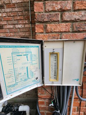
Jandy Aqualink RS
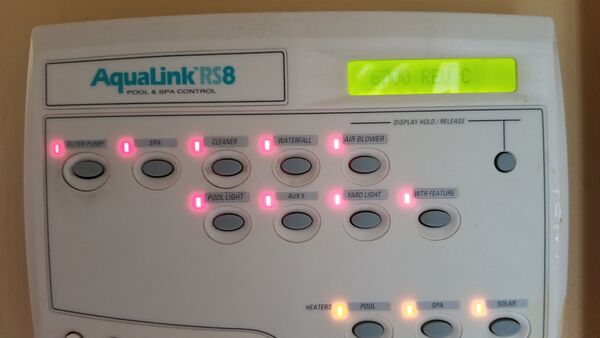
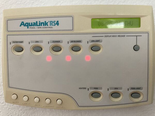
Jandy Aqualink RS systems provide automation for your pool, spa, and backyard. Aqualink RS is the full-featured version of the Aqualink product line. The AquaLink PDA and Aqualink Z4 products have different control devices, user interfaces, and functionality.
All programming, labeling, temperature settings, etc., are stored within an EEPROM (Electronically Eraseable Programmable Read Only Memory) chip. This chip is located on the PCB and will retain all settings indefinitely, even if power is lost for an extended period. To remove information from the system, either press the Cancel button to remove individual items or the Clear Memory item from the Menu to reset all items to their default settings. The battery attached to the PCB is only needed to keep the clock running during a power outage, so when power is restored, the time and date will be correct.
When pressed, the Reset button in the upper left-hand corner of the Power Center Bezel resets the Power Center microcontroller and changes the time and date to the default settings (i.e., 1:00 P.M. 01/31/96 WED). Pressing this button will not remove any programming, AUX labels, etc.
This Jandy Automation Selection Guide shows the family of modular components across the different Aqualink models—RS, PDA, and Z4.
Aqualink RS can be controlled by two wired control panels[1] - All Button or OneTouch - each having different user interface logic to perform the same tasks. Web-connected devices can control the Aqualink RS with the optional iAqualink 2.0 . Apps are available for devices such as Android®, iPhone®, iPad®, iPod Touch®, or any other HTML5 web browser device.[2]
Jandy Troubleshooting Manual for AquaLink® RSAll Button and OneTouch™ Control Systems covers many common problems.
Jandy Aqualink PDA
There is a world of difference between the Aqualink RS and PDA systems.[3] Namely, the RS system is internet accessible meaning you can access it from anywhere in the world from a web browser. Tech support can also take full control of your system if needed for troubleshooting or programming. It also allows Alexa control if you want (Alexa, turn on waterfall/light/heater, etc). In addition, with an RS system, you program from a web browser interface.
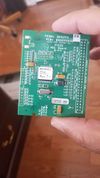
With a PDA system, you program from the PDA, which is super clunky (you will hate life). However, it is very easy to upgrade the PDA system to the RS. All it takes is a daughterboard (PCB) swap, which is about a 10-minute job.
If you upgrade a PDA system, you can keep or sell (or turn in for builder credit) the actual PDA and the PDA antenna (worth $500-$1000 on eBay). Either version of Aqualink should include the power center, as that is where the system itself is located. Upgrading from the PDA to RS is around $1k. It depends on whether you have the IQ20/30 antenna already. It's a little under $1k if you have the antenna and a little over $1k if you don't.
Many builders do not know the difference between the IQ20a and the IQ20-RS upgrades. IQ20a is just the WiFi antenna. This does virtually nothing for you. You still have a PDA-based system, but now with the ability to turn things on/off with your phone. Big deal. The IQ20-RS is the full PDA based to RS-based conversion, which switches roles and gives you Internet access (and makes the web interface your primary interface).
Quite frankly, the PDA-based systems are totally obsolete, and Jandy should discontinue them.
Aqualink Cabinet Configuration
The Jandy Aqualink physical cabinet comes in three different configurations. Two of the cabinets do not have a Load Center, while the other one does.[4]
- 6612F = This is a small power center that comes with 4 relays and has no room for additional ones. It does not have high-voltage breakers, so it would only be used when a subpanel is nearby and already supplying power to the equipment.
- 6613 = This is a medium-sized power center that comes with 4 relays and has room for up to 8 (just purchase Jandy 6581 separately if you need more). Like the 6612F, it does not have high-voltage breakers, so it would only be used when a breaker box is nearby already supplying power to the equipment.
- 6614-LD = This is the most common load center you see for installs. It has a low-voltage area on the left side to fit plenty of add-on boards such as JVA relays and smart JVAs. A high-voltage side has 12 slots to fit Siemens breakers. It comes with 4 relays and can fit up to 8 on that side (just purchase Jandy 6581 separately if you need more). You'd wire all your high-voltage into this box as it would be a subpanel for your entire pool.
The smaller boxes are used when there is already a sub-panel out there with breakers already supplying power to the pool equipment, and then that would wire into this box if you're doing a retrofit, but none of that has anything to do with it being an RS4/6/8. They may also be used as auxiliary power centers when you need to add more relays that do not fit in the existing power center. An RS4/6/8 can work with any 3 of these boxes.
The caveat is that if you get a 6612F, there's only room for 4 relays. If you need more, you'll need a bigger box, such as the 6613. Some people may not. For example, you can have an RS8 and use 4 relays, and use the additional Aux's on the RS8 to control valve actuators via relay boards, so you don’t need the extra 3HP relays. That means you could technically use the smaller 6612F box with a separate sub-panel but the best solution is a 6614-LD regardless of what RS4/6/8 is purchased.
If you already have a subpanel by your equipment pad or your equipment pad is your main breaker box, then 6612F or 6613 will work for you. The smaller one has only 4 relay spots, and the larger one can hold up to 8. Either of those will work with RS4, 6, or 8. You just need to decide how many 3HP relays you will use.
The recommended configuration, regardless of whether you already had a subpanel by the equipment pad, is the 6614-LD. If you already had a subpanel, then rip out the old one and replace it with the Jandy one for a much cleaner install all in a single box. There’s not much work required to do that.
There are times when a 6612F or 6613 makes sense, such as if your pool equipment breakers are in a meter main on the outside of your house (local code may vary) and you do not need a sub-panel but that's rare since pool equipment is typically set back too far from the meter main combo panel.
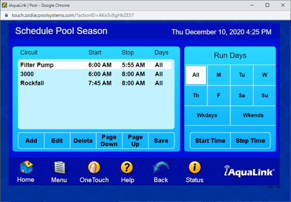
Running AquaLink Filter Pump 24/7
The AquaLink schedule needs a 5 minute off period. The AquaLink software apparently does not support true 24x7 operation.
Pumps
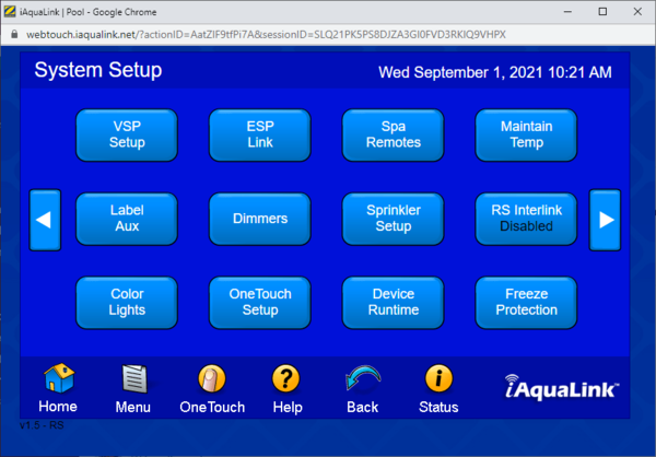
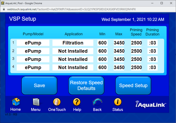
VSP Setup and Scheduling
In 2022, Jandy began implementing a change in addressing their VS pumps. The old way was to use dip switches to set one of four pump addresses. New pumps have a serial number the Aqualink pulls from the pump, and up to 16 pumps can be supported on one Aqualink system. Aqualink firmware Version W or later is needed for the serial pump addressing.
The Aqualink board Rev level determines which pump addressing is used:
- Rev O or later is needed for support of VS pumps
- Rev V or earlier with all VS pumps use addresses 1 through 4
- Rev W or later with old VS pumps use addresses 1 through 4
- Rev W or later with new VS pumps use addresses 5 through 16
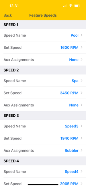
If you have pumps with serial addressing and Rev W or later, use the iAqualink phone app for setup. It seems that Jandy updated the iAqualink phone app with the new features but has not added them to the web iAqualink app. Also, the iAqualink phone app displays different color screens on the new firmware (yellow) than on the old firmware boards.
Note that with serial address pumps, the pump name includes the last four digits of the serial address. Anything that says pump 1863:name is a VSP speed setting, not a function. So pump 1863:spa is the spa pump speed, not the Spa function. Pump 1863:pool is a VSP speed setting. Don't schedule a pump name like that.[5]
You need iAqualink or the OneTouch controller to set up a VS pump. The All Button controller cannot do RS-485 control for a VS pump.[6]
You don’t ever have to mess with scheduling the VSP speed setting for most functions. You schedule the function(s) you want and the system automatically pulls the associated speed(s) from the VSP table.[7]
The functions of Cleaner, Spillway, and Spa Mode automatically turn on the filter/pump function, so you don’t have to schedule the filter/pump as a separate entry with the same timing. Practically, you will want to have a filter/pump schedule item that spans the whole time the pump is on, and then add the cleaner, spillway, or other functions as a subset of the overall time. In the example above, the filter/pump is scheduled to run for 24 hours a day except for a 5-minute stop.
With version W or later, pumps 1 through 4 are used for dip switch addressing, and pumps 5 and beyond are for serial addressing. If you have a serial address pump, it will be at pump 5 and not 1.
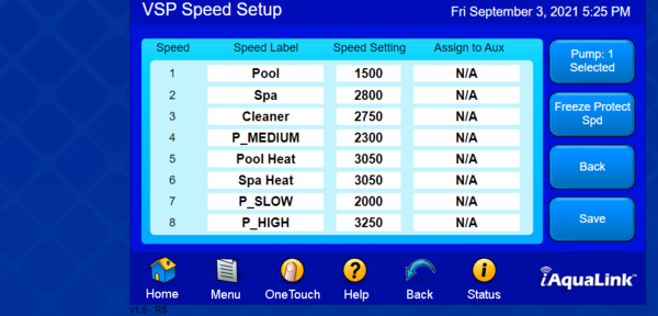
The VSP Speed Setup table has eight entries, and entries 1 through 6 are automatically associated with a function:
- When the filter/pump function runs, it automatically uses Speed 1 - Pool
- If the Spa mode is enabled, it uses Speed 2 - Spa
- Likewise, when the Cleaner function is active, it uses Speed 3 - Cleaner
- and so on with the spillover, pool heat, and spa heat functions.
- If you have a Solar system, you can have Speed 7 named Solar Heat. The system automatically changes the pump speed when the Solar Heat is on.
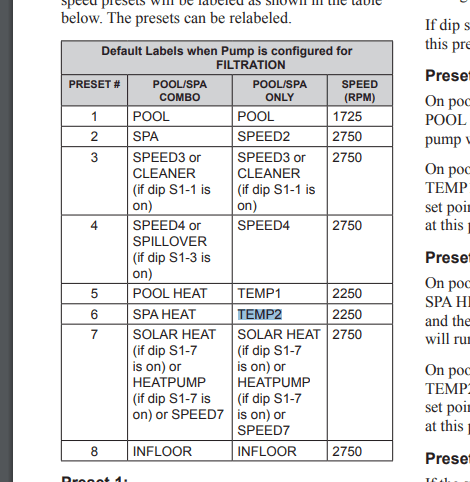
The default VSP Speed table labels are shown in the manual and vary with the type of system you have and the dip switch settings:
With the Pool, Spa, and Solar Heat, it should be noted that the pump only changes its speed setting when the heat is active. If one of the Heat settings is enabled but off because the pool/spa has reached temperature, the pump will switch back to Speed 1 (pool) or Speed 2 (spa) if that mode is active.
In general, you should never have to add separate VSP speed items to your schedule unless you are doing something special. Most of the operating functions already have one of the eight speeds associated with them, so when you enable the function, Aqualink pulls the associated VSP speed automatically.
When any of the schedules are running, you can also manually select the VSP speed and choose any of the eight speeds or enter a custom speed. The pump will go faster or slower when you set the speed. In the case of the manual entry, the “fastest active speed rule” no longer applies, and the pump will go to the speed setting you enter and stay there until the schedule next changes a function that affects the speed.
One exception to this is when any of the Heat modes are running. If the Pool Heat is on and you try to manually change the VSP speed, you may increase the speed but may not go lower than the associated heat speed setting. This is to protect the heater from operating with too low a water flow.
Another reason for not using VSP speed settings in your schedule directly is that they can be confusing. Let’s say that I run the Cleaner function for an hour, and later in the day, I want to run the pump at Cleaner Speed but with the cleaner off. To enter this, you would put the Cleaner function and the VSP speed of the Cleaner in the schedule for the time you want each to run. Now you will have two Cleaner items in the schedule: one that runs the cleaner, booster, and JVA valve if you have it with the pump running at the cleaner speed, and the second cleaner item that changes the pump speed. These both look the same in the schedule; they each show up as Cleaner, which can be confusing as they do two different things.
If you want to run a different speed in a schedule for some reason, I would use Speeds 7 and 8, which are not associated with anything, and name them uniquely. You can use the name Speed 7, or in my case, I have named Speed 8 with Speed 2100. Then, if this VSP speed is added to a schedule, the name is unique and won’t be confused with any associated function.
How to link a VS pump to an iAqualink Aux button
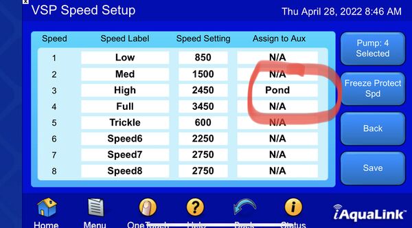
Go to the pump's edit speeds screen, pick one speed you want linked to the Aux output, and then assign that speed to an Aux output. That output will then show as “on” when the pump is on, and selecting that button will turn the pump on to that speed.[8]
Controlling Century VGreen EVO VS Pump Motor
Century VGreen EVO motors are available in 1.30, 1.65, and 2.25 THP models with square and c-face flange. Look for the Century Connect label on the packaging:[9]
The latest Century VGreen EVO motors with Century Connect support will automatically communicate with Jandy, Pentair, or Hayward automation systems. Century changed the motor’s firmware and began to advertise its “Century Connect” feature about 18 months after the introduction of the EVO motor.
Earlier EVO motors have a custom set of RS-485 commands incompatible with any of the big 3 automation systems:
- The VGreen 165 is the same motor used on an earlier model of the Jandy Flo-Pro165 pump, Enabling the Jandy Aqualink RS-485 Protocol on the Vgreen 165 motor describes how to get the VGreen 165 motor connected to Aqualink.
- The EVO225 is a different motor than the Vgreen 165, and these tricks do not work on it
- For the first two or three years, the Vgreen and EVO motors did not officially support anything other than native Modbus protocol, which only worked with their proprietary Vlink controller.
The Aqualink RS communicates with its RS-485 peripherals via a poll-response protocol. The VSP motor must see a poll before it can respond.
Once you tell the Aqualink RS that a VSP pump is out there (via the VSP setup page), the Aqualink RS begins polling the motor’s address. Century Connect can then see the polling and figure out what system it is attached to.
Controlling Pentair Intelliflo Pumps
Note that if you are replacing one Intelliflo VS pump with another pump you need to change the pump to ePump and then change it back to Intelliflo VS to get Aqualink to recognize the new pump.[10]
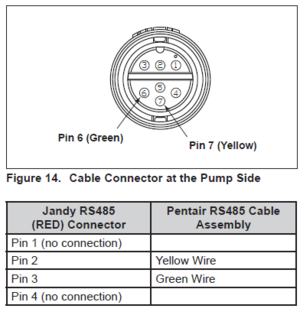
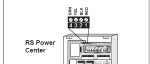
Jandy Aqualink Installation Manual[11] section 3.2.7 describes how to connect a Pentair Intelliflo pump to the Aqualink. You need to match up section 3.3.4 in the Aqualink manual...
with 3.3.3....
| Pin Number | Pentair | Jandy | Function |
|---|---|---|---|
| 1 | Red | Red | +15V |
| 2 | Yellow | Black | +Data |
| 3 | Green | Yellow | -Data |
| 4 | Black | Green | Ground |
which leads you to conclude that Pentair yellow wire goes to screw 2 Aqualink BLK and Pentair Green wire goes to Aqualink screw 3 YEL.[12] And the Aqualink connection from the IntelliFlo pump looks like...
While the Aqualink RS can control an Intelliflo VS pump it cannot control the VF functions of a VSF pump.
At one time Jandy's F/W was made to talk with the IntelliFlo VS. Then Pentair developed a new pump that was both a VS and VF pump, the VSF. Jandy's F/W has never been updated to drive the VF portion of the VSF pump.
Speculation is several years ago the Big Three (Hayward, Jandy and Pentair) decided to share their RS-485 code, so that they could control each others equipment. Not sure why that did not continue, but as time went on, the firmware running all these systems has changed, but the Big Three no longer keep this interchangeabilty in mind when they update their firmware.[13]
This is the main reason that we always recommend the same brand for products that need to "talk" to each other. It just makes things easier for installation and warranty issue.
Pump Turns Off After Cycle
Are you using a OneTouch button to operate a feature? OneTouch buttons end with an ALL OFF command and your normal schedules do not resume.[14]
It is the same thing as you manually turning off your pump. It will remain off until the next scheduled pump start time. Instead, setup schedules for the individual components needed.
Spa Drain/Fill
The spa water level can be drained or filled from the outdoor panel. SPA DRAIN and SPA FILL buttons are on the top left.
- Put the panel in SERVICE Mode
- Press FILTER PUMP
- Press SPA DRAIN. Turn off the pump when the spa is at the required level
- Leave the panel in SERVICE mode while you do repairs
- Press SPA FILL.
- Press FILTER PUMP
- Turn off the FILTER PUMP when the spa is full
- Return the panel to AUTO
Auxilary Functions
The dip switches are on the upper left of the load panel and to the control panel's left. See section 7 of the AquaLink RS Control Panel Installation Manual.[15] Older AquaLink boards have a single set of dip switches. Newer boards have a second set of dip switches with the upper set marked S1 and the lower set marked S2.
Caution: Always turn off all circuits and then turn off the power before moving DIP switches. If AUX 1, 2, or 3 were programmed to operate automatically, clear the programs before turning on the appropriate clip switch.
Cleaner
S1 Dip switch #1 makes AUX1 be labeled CLEANER.
If your pressure cleaner is powered by a pump, the booster pump should be connected to a relay connected to AUX1.
If a non-booster pump cleaner is installed, plug the JVA into the cleaner JVA socket.
Spillover Mode
If you have a pool and spa, you can enable the Spillover function with S1 dip switch #3 on the main panel. When S1 switch #3 is on, AUX3 becomes the spillover control. If you have any relay connected to AUX3, you need to move it to an available Aux position.
With Spillover turned on by AUX3, the POOL/SPA return valve will move to the SPA position. Water will be suctioned out of the pool through the skimmers and returned to the spa.
The cam on the return actuator may need to be reset to fully close the spa return when in POOL mode.
Automating a Water Feature Valve
You may have a water feature that is manually controlled by a diverter valve. You can control that valve from your Aqualink in three ways:
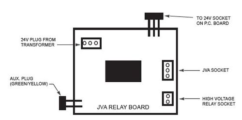
1—Jandy has a 5254 Jandy Valve Actuator Aux Relay Board that connects a JVA to a high-voltage relay socket.
2 - If you are not using a cleaner pump connected to AUX1, you can...
- connect the waterfall JVA actuator to the CLEANER socket - put dip switch 1 ON that enables the cleaner function - if you have something connected to AUX1, you need to move it to another AUX relay as AUX1 becomes the cleaner - you will find AUX1 is labeled CLEANER, and I believe you can rename it to WATERFALL
When you select AUX1, the JVA should turn and enable your waterfall.
3—This circuit allows you to control an actuator using a high-voltage AUX relay. AUX relays use two wires: 24 VDC and ground. Valve actuators use three wires: two 24 VAC lines and ground. AC on one line turns the valve one way, and AC on the other line turns the valve the other way.
You could use the AUX relay to control the 24 VAC so that it will turn the valve using the following circuit. But normal AUX relays won't work as they do not have any Normally Closed contacts. You need a relay that has NC and NO contacts, such as the Pentair 520198, 2-speed relay, which has NC and NO terminals and will plug into a Jandy, Pentair, or Hayward board.
If you have a pool only system, you can assign the Intake and Return to an AUX button[16]
Controlling a 2 Speed Pump
You need the Jandy 2-Speed Relay Kit for Pumps JDY6796 and the AUX2 relay free.
S1 DIP #2 ON- AUX2 Controls Low Speed of Filter Pump Turn this switch ON if you want to control both speeds of a two-speed filter pump. With this switch on, the filter pump button on the AquaLink RS control panel will control high speed and the AUX2 button will control low speed.
Timer AUX Cycles
The labels "TIMER AUX," "AIR BLOWER," and "FILL LINE" are 30-minute time cycles.
If you don't want your air blower to turn off automatically after 30 minutes, use a different AUX label. The 30-minute off timer protects the blower motor from overheating.
In Floor Cleaning System (IFCS)
When "In-Floor" is enabled in SETUP, the solar JVA output on the iAquaLink board can be used to rotate the IFCS value every 20 minutes. With a VSP speed schedule 8 is used when IFCS is enabled.
iAquaLink with In-Floor Cleaning System discusses how a creative member setup his iAqualink with IFCS enabled and got around the system always running the VS pump at the high IFCS speed.
Factory Adjustment Mode - Display Solar Temperature
S1 DIP #5 ON puts the Aqualink RS panel into Factory Adjustment mode.[17]
- Start the Aqualink Phone App and record the Air Temp setting.
- Turn off power to the Aqualink controller. This is required because DIP switches are only sampled during initialization.
- Turn on S1 Dip Switch #5 which turns on the Factory Adjustment mode as described on Page 45 of the Aqualink RS Installation Manual. This disables any Temperature Delays and Displays Solar Temperature.
- Turn on power to the controller and wait a few minutes while the system initializes.
- From the Aqualink Phone App select the WEB page and then select the Status icon on the bottom of the Home Page.
- The last line on the Status Page should read “Status: 0B”. This indicates the system is in the Factory Adjustment Mode and Solar Temp is now displayed instead of Air Temp on both the App and Web Home Pages.
- Compare the Solar Temp reading with the Air Temp reading you previously recorded. They should be within a couple of degrees if they are both in direct sunlight. If one of them is in the shade then there will be a larger difference but the two values should be in the same ball park if the Solar Sensor is working properly.
- After you have checked the Solar Sensor you need to put the Aqualink system back into the normal configuration mode by reversing the previous steps: Turn off power, turn off the S1 Dip Switch #5, and turn power back on.
- You can check that you are back into normal mode by verifying that the “Status: 0B” is not present in the WEB page Status display.
Aqualink Freeze Protection
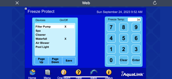
In iAqualink, you select which equipment is enabled for Freeze Protection. If both are enabled, the system switches between the Spa and Pool every 30 minutes.
Freeze protection for the filter pump is on by default and cannot be disabled. The Freeze Temp can be adjusted between 34°F (1°C) and 42°F. The default freeze protection activation temperature is 38º F (3°C) and will deactivate within two degrees.
Freeze protection uses the Aqualink air temperature sensor. Some members have found they need to relocate the sensor to prevent Freeze Protection from cycling on and off every few minutes.
If the air temperature sensor does not read correctly after relocation, it should be replaced (Jandy PN 7784). Testing a temperature sensor is discussed in Temperature Sensors.
The right-hand button on the VSP Speed Setup page allows you to set the speed at which a variable-speed pump runs during freeze protection.
Jandy SmartJVA
Jandy told a member that Aqualink Rev Y no longer supports Smart JVA functionality.[18] If you stay on REV R or before the SMART JVA will continue to work.
The SmartJVA add-on board allows Aqualink owners to set in real-time the amount their automated valves (JVAs) are open from 0 to 100% in 5% increments. It requires Rev R or newer.
Jandy SmartJVA Module **HOW TO GET IT WORKING** describes how to get the SmartJVA working. The thread notes that some of Jandy's installation instructions are not correct.
Dual Speed Pump Relay
You need the Dual Speed Pump Relay Kit—6796 to control a two-speed pump. This kit replaces one of the high-voltage relays and switches power between the high-speed and low-speed lines. It has a 2-pin connector that plugs into the PC board relay socket.
The relay type is SPDT, and the maximum current is 20 amps. The pump should have a motor of no more than two horsepower at 220 VAC.
You program the entire duration you want the pump on at high speed, then program the low speed as a subset.
The Zodiac 6796 2-Speed Motor Relay Replacement Kit is designed for use with Zodiac Jandy AquaLink RS Control Systems and is also compatible with Zodiac Polaris EOS and Sol models.
The Two Speed Relay operates with a Standard Relay to operate a two-speed pump/motor. The Standard Relay is the On/Off relay, and the Two Speed Relay is the switching relay. Activating the relay coil for the Standard Relay will complete the contact circuit between Line 1 and the motor common and Line 2 and the Two Speed Relay's Common. If the Two Speed Relay's coil wires are deactivated, its contacts connect its Common terminal and its Normally Closed terminal, and the motor runs at High Speed. When the Two Speed Relay coil is activated, its contact makes the connection between its Common contact and Normally Open contact, and the motor switches to Low Speed.
If the Two-Speed Motor is the filtration pump, plug the relay coil wires for the Standard Relay into the Filter Pump Relay socket. Next, plug the Two-Speed Relay's coil wires into Auxiliary 2. Finally, turn on DIP switch 2 to set the circuitry to two-speed operation.
RS-485 Connections
The Aqualink RS board has one or two RS-485 connections. You can connect at most two sets of wires to each RS-485 connection. Depending on whether your panel has one or two ports, you can have two or four devices hooked up to the main PCB.
The Jandy AquaLink RS Multiplex Board (6584) connects additional devices beyond what the main PCB can handle. It mounts on the left in the Aqualink panel. It's a green circuit board with four red 4-wire connectors. You run a 4-wire from the top port to a port on the multiplex. Then, you connect your other devices to the multiplex board. It's the same as running multiple wires to the same connector. It's a bit pricey, so it's probably not worthwhile.
An RS-485 port must have the correct firmware level to work with a Jandy device. The PCB must also have rev. N or higher to be used with an LXi/JXI heater.
Communication between the Aqualink RS and its RS-485 peripherals is via a poll-response protocol. The RS-485 device, such as a VSP motor, must see a poll before responding.
Aqualink to Heater “Smart” Communication via RS-485
With the RS-485 four-wire smart setup, you don’t have to set your heater to its maximum setting of 104 degrees. The set point on the heater display will now match the temperature you have the Aqualink set to. And if you have a spa, the heater will now display either the spa temp setting or the pool setting depending on which heat mode is selected on the Aqualink.[19]
You also get more representative information on the heater display itself, but from the Aqualink user interfaces, it looks the same as before. The Aqualink system will give you a diagnostic message if the heater has any faults.
NOTE: Only an AquaLink® RS System with firmware revision “N” or higher will support the heater interface. Refer to Table 6 along with Figure 18 and Figure 19 in the JXI Heater Installation Manualto determine the REV of your system’s firmware. If it is “N” or higher, continue with these procedures. If it is MMM or lower, follow the procedures in Section 7.2 of the Installation Manualfor connecting to a remote TSTAT
Jumpering Jandy ePump RS-485 control
You can test the pump drive using the RS-485 jumper method. Using small sections of 22 AWG wire, jump pins 1 to 3 and 2 to 4. These wires can be made by cutting off a section of the RS-485 wires. Re-install the connector and attach the access cover. Apply power to the motor. The motor should spin at 2600 RPM indefinitely. If the motor works, there is a problem with the RS-485 line or with the controller.[20]
iAquaLink Wireless Connectivity
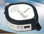
iAquaLink is Jandy's add-on device to add wireless connectivity to Aqualink. There are three versions of iAQualink - an older version called iAqualink IQ900 and a version called iAqualink 2.0 or IQ-20, and a new for 2021 iAqualink 3.0. The new iAqualink 3.0 has a newer radio transceiver with all the same functionality of the 2.0 version. Still, the website claims that the 3.0 version has better support for mesh WiFi routers as version 2.0 had some issues connecting to them. For most folks the 2.0 iAquaLink is fine.[21]
Version 1 AquaLink is the blue web connect device, and version 2.0 is the white web connect device. You now want iAquaLink 3.0, which has improved connectivity over 2.0.
You need to know what revision number your system is at to know what kit to order.
iQ20-A iAquaLink Kit Includes:[22] iAquaLink 2.0 Web Connect Device.
iQ20-RS iAquaLink Kit Includes: iAquaLink 2.0 Web Connect Device. Main Power Center Board and AquaLink RS Firmware Upgrade.
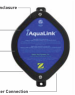
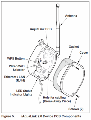
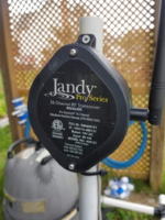
The web connect device consists of a:[23]
- J box housing
- PCB board with the electronics
- an outside vertical antenna
iQ30-RS has the same equipment as iQ20-RS with an improved 3.0 antenna - Zodiac iAquaLink 3.0 iQ30-RS Web Connection Upgrade Kit
The Web Connect device can be connected to a home network using a wired Cat-5 cable or a using WiFi. Version 1 device supports 802.11b WiFi connection only[24] while the iAquaLink white 2.0 device supports 802.11b/g. It appears they are both 2.4Ghz and not 5Ghz WiFi and do not support 802.11n or ac protocols.
Version 1 supports WEP, WPA, or no encryption during setup while Version 2 has a WiFi Hotspot Method or uses WiFi Protected Setup to select the correct encryption method.
There does not appear to be any Zodiac/Jandy document that confirms the WiFi specifications, protocols, or encryption methods supported by iAqualink 2.0. It may take some trial and error on your WiFi router or access point to find the settings that work with the iAquaLink web connect devices.
SELECT THE CORRECT iAQUALINK 2.0 UPGRADE KIT
Use p/n iQ20-A to upgrade these systems:
- AquaLink RS - Rev R & newer
- AquaLink PDA - Rev 6.0 & newer - If you have the Aqualink PDA, and not the RS, the Web Connect Device alone just adds wireless capability to your PDA system. You still use the PDA to program everything. This basically adds SmartPhone ability to turn things on and off. It is a wholly useless upgrade.
- AquaLink Z4 - all revisions
Use p/n iQ20-RS or iQ30-RS to upgrade these systems:
- AquaLink RS - Rev QQQ & older
- AquaLink PDA - Rev 5.0 & older
If you have a Aqualink PDA system the iQ20-RS or iQ30-RS changes your system from being PDA based to being web-based. You will no longer use your PDA to program Aqualink. And that functionality will disappear from the PDA menu options. This is a good thing. Like said above, you will never use your PDA again and it you want to recoup some of your money, the going rate for PDAs are around $500 or so. If you include your PDA antenna you could probably get $700 for it all. The IQ20-RS upgrade consists of a WiFi antenna and a new daughter processor board. Once installed, Jandy will be able to control your system remotely if you call for help. Be advised, if you lose Internet access, you will not be able to change any programming on your local system including scheduling. Scheduling will still run, however. And you will only be able to turn things on/off if you have a wired panel (like a OneTouch) or the PDA as a backup.[25]
iAqualink 2.0 Replacement Antenna
The antenna on the outdoor iAqualink transceiver disintegrates from the sun's UV rays on the plastic parts. The antenna can be replaced every few years with a 2.4GHZ WiFi RP-SMA Male Antenna.[26]
Some older iAqualink 2.0 boxes have antennas that are not removable and are soldered onto the board. These boxes need to be replaced when the antenna breaks.[27]
iAqualink iQ-900 Replacement Antenna
The antenna is a whip type. When you open the box up, you will see that it is mounted through the box and held in place by a nut. The cable leading from the antenna comes up through a hole in the PCB to a connect called a UFL and is plugged into the Wi-Fi modules mating UFL.[28]
To Disassemble:
- Disconnect the 4 wires (RS-485) to the Aqualink so that the iQ900 is not powered up.
- Open iQ900 box if you haven't yet.
- Gently on the UFL connector (not the cable), disconnect the antenna's UFL from the Wi-Fi module. You can use a plastic tool to lift the connector off the mating connector on the board.
- Remove the 4 screws holding down the PCB to the plastic box and remove the PCB from the box. The 3 LEDs are instead into the side of the box so you will need to shift the PCB a little before lifting the PCB out of the box.
- Using a 3/8" open ended wrench loosen and remove the nut and washer that is holding the antenna to the box.
- Remove the antenna from the box. There will be an oring on the the outside for sealing the antenna to the box. this might need replacing.
New parts:
- Digi-Key: ANT-2.4-PML-UFL-ND (The cable will be longer, but that can be lay in the box with not problem).
- O-Ring: 008, 4.8mm ID, 8.6mmOD
To Assemble:
- Insert the new antenna cable through the oring and slide it down to the thread part of the antenna.
- Insert the antenna cable through the hole in the box.
- Insert the antenna cable through the locking washer that came with the new antenna and slide it down to the thread part of the antenna.
- Insert the antenna cable through the nut that came with the new antenna and slide it down to the thread part of the antenna.
- Thread the nut onto the antenna and tighten. Check the orientation of the antenna and be careful not to over tighten if the threads on the new antenna are plastic.
- Now lay the extra cable length around the box so that the UFL ends up near the hole in the PCB that it will go through. Do not folder or kink the cable.
- Insert he cable through the PCB and connect the UFL connector of the cable to the UFL mating connector on the Wi-Fi module.
- Insert the PCB back into the box. You will need to offset the board so that you can align the 3 LEDs with the holes on the box.
- Screw down the PCB board to the box.
- Close the box up and reconnect the 4 wires (RSS-485) to the iAqualink.
The iQ900 will power up and should connect to the access point.
Estimate cost is ~$12 for antenna ( not including shipping and tax) O-ring: less than a $1.
iAqualink Working with Mesh Routers
See Wireless fix for iAquaLink / Eero mesh issues for how a member used a TP-LINK wireless range extender for iAqualink to work with an Eero mesh network.
Problems have been reported with iAqualink connecting to mesh routers like Eero.Getting a stable WIFi connection includes assigning a fixed IP address to iAqualink, unplugging "extension" units (nodes) and setting the router to only broadcast 2.4 GHz. After the eero is "simplified" to a single node broadcasting on a single frequency - follow the normal reset procedures (turning the switch from Wired to Wireless, going into the network on an iPhone, and setting up the iAquaLink connection).[29]
Eero support commented that iAquaLink was seeing too many connections with the same ID (because of how the mesh works) and getting confused. By using only one node, iAquaLink saw only one connection on each network. Use the Guest network to keep an unsecured device off the main network.
One member suggests you unplug all Eero units from the power except the gateway. In eero app go to settings, troubleshooting, my device won’t connect 2.4ghz this will give you 15 minutes of only 2.4ghz band. Now do the toggle Wi-Fi/wired in the iAquaLink few time to clear memory, and continue to connect as usual, if you don’t have wiring or hardware issue with the iAquaLink, you should get connected.[30]
Some people have found that the easiest fix is to install a simple 2.4Ghz WiFi router or access point for the iAqualink connection.
iAqualink Connecting to EERO
For an Eero, the process is to enable guest access, then connect your antenna to the guest network. At this time, there is not another way to connect as Eero otherwise only supports WPA2 and your antenna requires WPA.[31]
To connect your antenna using the hotspot method you’ll want to;
- Take the cover off of the antenna with a Phillips head screwdriver (+)
- Toggle the black toggle in the center over to wired, then back to WiFi
- Go to your WiFi settings on your phone, there should be a network called 'iAqualink-xxx' connect to this
- A login page should appear shortly after connecting, this will pull up all the WiFi networks the antenna sees to connect with
- Select your Guest WiFi network, When inputting your password, be careful, the keyboard auto-caps the first character, make sure to double-check your password
- The antenna will now try to connect, you can verify if it's connected by checking the status lights. There are 3 lights on the outer left side of the antenna (Red, Yellow, Green) If all 3 are lit, the antenna is connected.
iAqualink Hotspot Setup Connection with Android Phone
If you have connection problems using the iAqualink Hotspot setup with an Android phone see if iAqualink 2.0 Connection Problem fixes the problem.
Aqualink LED Light Support
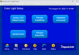
Aqualink supports the following color changing LED lights:
- Jandy WaterColors
- JandyColors
- Pentair IntelliBrite
- Pentair SAm/SAL
- Hayward Universal
Actual support once installed may vary, however.
Aqualink Temperature Calibration
Go to MENU>SYSTEM SETUP>TEMP CALIBRATE. This should allow you to calibrate +/- 4 degrees.
Aqualink Turning Off All Equipment
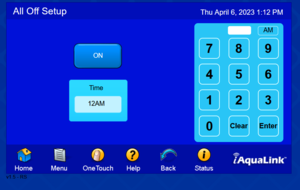
There is a setting that can be enabled to turn off all equipment at a certain time. This is independent of the schedules.
Look under the System Setup menu for the All Off Time menu item and see if it is enabled.
Aqualink Relays or JVAs Not Working
You could have a failed driver chip. The Driver Chips can be thought of as a series of small relays. When one of the Driver Chips receives a signal, it closes a contact that passes 24 VDC to the appropriate relay coil socket, in this case, AUX 1. Each relay driver chip activates a specific set of relay coil sockets (see the chart below). If a Driver Chip fails, it is usually caused by either shorted relay coil wires, a shorted relay coil, or a relay not designed for the 24 VDC coil voltage (i.e., 24 VAC rather than 24 VDC).[32]
The relay coil provides resistance (approximately 300 Ohms); the driver chip circuit will be damaged if there is no resistance. That can be caused by a short in a relay coil.
| Driver Chip in U9 socket activates | Driver Chip in U10 socket activates |
|---|---|
| Relay Socket for Filter Pump | Relay Socket for Electric Heater |
| Relay Socket for Auxiliaries 1 through 7 | Solar Booster Pump Socket |
| Relay Socket for Spare Auxiliary | All JVA Relay Coils |
| Low Voltage Heater Relay Coil |
The driver chips are Zodiac P/N 3814 or ULN2803A chips. ULN2803A is available from Digikey, Mouser, or Newark. ULN2803A is a commonly used, 8-bit NPN integrated Darlington transistor array chip with a high-current and high-voltage relay array driver that can handle eight relays simultaneously.
The Aqualink PCB has two socketed chips. In the picture below, the chip in the blue circle controls the valve actuator relays, and the chip in the yellow circle controls the high-voltage relays.[33]
When replacing the ULN2803A chip, note the orientation of the cutout on one edge and install the new chip with the same orientation.
The Power Center PCB is the brain of the system. The microcontroller on the PCB is constantly sending signals through the communication wires to the Controller and polling the system to determine which circuits should be on and which should be off. When an equipment button, such as Auxiliary 1, is pressed, impulses are sent via the communication wires (yellow and black) between the Power Center microcontroller and the Indoor Controller microcontroller. If all impulses received at the Power Center microcontroller are consistent, the system then looks at the DIP Switch settings to determine if an option for this circuit has been set. If the DIP Switch settings do not indicate a delay is needed, signals are sent back to the Controller to turn on the appropriate LED and display the ON message. At the same time, a signal is sent to one of the two Driver Chips on the Power Center PCB.
Spa Side Remote Switch
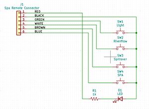
The four Spa Side Switch buttons send a momentary signal to the Power Center PCB. Each button sends a signal down one wire with the circuit completed through the common wire. The operation of each button may be tested by disconnecting the Spa Side Switch from the PCB and with a meter set to continuity measure between each button wire and the common (black) wire, while holding the button down.
If any button on the Spa Side Switch is held down for more than 5 seconds, the AquaLink RS's microprocessor considers this a shorted button and will ignore its signal. When the button is released or repaired, and a "shorted circuit" no longer exists, the microprocessor will again recognize all buttons. The LED in the center of the switch will be on solid when the spa is on, flashing fast when heating, and flashing slowly when in cool down mode.
To troubleshoot the four button spa aide remote remove the Spa Side Switch (6 pin) terminal bar from the printed circuit board. Set your multimeter to read continuity (or resistance).
- Ensure No Shorts - Measure between the black (common) wire and each of the button wires. If there is continuity between any of the two (without depressing a button), the switch is shorted; replace it.
- Ensure Continuity - Do this same test again except this time have a helper hold down the button while you test for continuity. For example, measure between black and blue while helper holds down button
Smart (Alexa) Spa Remote Jandy 8 (Emulates Jandy 8 button spa remote)
This is a third party board that connects to the Aqualink to give wireless and Alexa voice control of 8 functions on your Aqualink.[34]
Smart (Alexa) Spa Remote Jandy 8 (Emulates Jandy 8 button spa remote)
Jandy AquaPalm Pro Series Wireless Handheld Remote
The AquaPalm is an add-on wireless remote for the Aqualink RS system and AquaLink Touch, OneTouch and All Button Control Panel Interfaces. It consists of the remote PDA and an 18 channel J-box transceiver that is different then the iAqualink J-Box transceivers.[35]
Jandy calls the same product both the AquaPalm Wireless Handheld Remote (AQWHR18) and the Jandy Pro Series Wireless Handheld Remote. It consist of:
- R0444300-- Handheld Remote Assembly Replacement Kit which is the PDA
- R0687300-- 18 Channel Handheld Remote Replacement Kit
The AquaPalm works with an AquaLink RS System ONLY, software revision “M” or later.[36]
The AquaPalm has a waterproof housing that floats; large backlit display and buttons; 500 foot range; and runs for months on 2 AA batteries.
The AquaLink RS AquaPalm will stop communicating anytime interference (such as a 900 MHz device) prevents a valid signal transmission. When communication is lost the AquaPalm Handheld Remote will lock on the startup screen until a good link is again achieved, usually within a few seconds. If communication is not reestablished within a few seconds or if this happens often, use the troubleshooting information on page 18 of the AquaPalm Installation and Operation Manual for suggestions.
Controlling Aqualink RS System with cheap PC hardware
How-to: Controlling Aqualink RS System with cheap PC hardware describes how to use the Aqualink Simulator on a PC with a RS-485 adapter to control an RS system.
Adding simple local controls to Jandy Aqualink RS
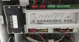
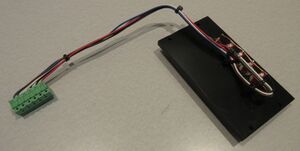
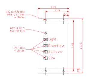
Adding simple local controls to Jandy Aqualink RS describes how to build the equivalent of the 4-Button "SPA Side Remote" into the control panel.
How to Upgrade Jandy Aqualink RS4 to RS6?
Replace the CPU board.[37] Always some on ebay but be careful of warranty issues. The are very easy to swap out takes like 10 minutes. System will need to be totally re-programmed when done. The instructions that come with them explain what to do. Make sure to get a current rev though a lot of people sell their old boards when they upgrade.
Here are the Zodiac/Jandy part numbers for the various RS CPU boards:
- Pool or Spa Only (1 body of water)
- R0466806 (RS/4 AUX)
- R0466805 (RS/6 AUX)
- R0466804 (RS/8 AUX)
- Pool & Spa Combo (2 bodies of water; shared pump/heater)
- R0466803 (RS/4 AUX)
- R0466802 (RS/6 AUX)
- R0466801 (RS/8 AUX)
AquaLink RS Conversion Kit for Pentair Enclosures
Jandy has developed a kit to retrofit Aqualink RS controls into a Pentair EasyTouch, IntelliTouch, or IntelliCenter enclosure.[38] The kit includes the iQ20 Web Connection unit although you are likely to want iAqualink 3.0 connectivity.
Note that the conversion kit installation manual says:
- It is not recommended to use this conversion kit in conjunction with Pentair integrated Saltwater systems such as Intelichlor, or iChlor.
- For configurations which have Pentair integrated Saltwater systems, replace the salt system with Jandy AquaPure or TruClear.
How to Determine the Revision of an Aqualink System
If you have the Aqualink All-Button Panel then MENU -> SYSTEM SETUP(press ENTER) -> DIAGNOSTICS(press ENTER)
If you have the Aqualink OneTouch Panel then MENU/SELECT(press SELECT) -> SELECT (for HELP) -> DIAGNOSTICS (press SELECT).
Jandy Aqualink PPD/CPU Revisions
This list provides detail and years behind each of the PPD revisions from Jandy.[39] Additional detail on the changes in each revision can be found in AquaLink RS Software and PCB Revisions Nov., 2011.
- A Programmable Peripheral Device (PPD) with revision letter C to HH will operate with all PCBs with a 44 pin socket.
- A Revision I or II PPD will only operate with a PCB which has a 44 pin socket and is a Revision I PCB.
- A Revision J or newer PPD will only fit into a PCB with a 52 pin socket (second generation of PCB).
- 1994-Rev. A = Alpha testing.
- 1995-Rev. B = Beta testing.
- 1996-Rev. C = First production AquaLink RS.
- 1996-Rev. D = Allowed Cleaner JVA socket to be assigned to an auxiliary by turning on dip switch 7.
- 1996-Rev. E = Programmed ON times not recognized after freeze protection activates.
- 1996-Rev. F = RS 2/6 Sharing a heater support, light dimming on RS 4.
- 1997 – Rev. G = First support for SpaLink RS, Cleaner JVA can be assigned without turning on dip 7.
- 1997 – Rev. GG = Cancel button locks-up system.
- 1997 – Rev. GGG = Correction to GG.
- 1998 – Rev. H = First support f or LX / RS 485 connection, memory expansion to 128K of ROM, SpaLink reads pool temperature and OFF when the system is not on.
- 1998 – Rev. HH = Corrects time calibration problem with Rev. H.
- 1998 – Rev. HH 232 = Support for RS 232 Serial Adapter.
- 2000 – Rev. I = First support for OneTouch, includes serial adapter support. Note Rev I will only operate in a Rev. I PCB.
- 2000 – Rev. II = Corrects problem with auxiliaries assigned to f reeze on OneTouch.
- 2002 – Rev. J = Change to 52 PIN PPD and new socket on AquaLink RS PCB.
- 2002 – Rev. JJ = Corrects problem with auxiliaries assigned to freeze on OneTouch.
- 2003 – Rev. K = Support for FlowLink, items manually turned on will reactivate after going to Auto/Service/Time Out.
- 2004 – Rev. L = Color Light Control, PC Docking, Laminar Light Pulse Control (LPC4), Chiller/Heat Pump operation, Run Time (circuits can be set to run manually f or 1 to 10 minutes or for 10 minutes to 2 hours in 10 minute increments). Will communicate directly with AquaPure Chlorine Generator only.
- 2006 – Rev. M = Support for AquaPalm wireless remote, Change chlorine production from AquaPure. AquaPure (revision must be 11230A05 or newer). Assign OneTouch buttons to SpaLink RS buttons.
- 2006 – Rev. MM = Corrects problem when entering into lights labels.
- 2006 – Rev. MMM = Corrects problem associated with daylight savings which caused the AquaPalm to jump lines. Light dimming can be adjusted from AquaPalm.
CPU REVISION CHANGES
- 2007 – Rev. N = Complete change to PCB. The operating chip is no longer a PPD, it is now a CPU (Central Processing Unit) board. The AquaLink RS can be connected via the RS 485 line to a Jandy AE Heat Pump &/or a Jandy LXi Gas Heater.
- 2008 – Rev O = Communication with Variable Speed pumps.
- 2009 – Rev P = Communication with ChemLink, LM3, AutoClear Plus & DuoClear.
- 2010 - Rev Q = first support for Touch Screen panel.
- 2012- Rev R = internet control of Jandy Aqualink system via smartphone or web
- 2013 - Rev. T.2[40]
- ???? = Rev V = Rev V and earlier, manufactured prior to mid-year 2022, support up to 4 variable-speed pumps using Dip Switches 3-4 on the pump.
- 2022 - Rev W = Aqua-link RS systems using Rev W and later, manufactured after mid-year 2022, support up to 16 variable-speed pumps that utilize a preassigned PUMP ADDRESS.
- ???? - Rev Xg - unknown
- ???? - Rev Y = Jandy Infinite WaterColors LED Light Controller requires Aqualink Revision Y or later.[41]
- 2024 - Rev Yg = Jandy added the ability to have 24 virtual auxiliary assignments.[42]
Home Automation control of Aqualink
AqualinkD is a daemon to control Jandy Aqualink RS pool equipment from any home automation hub (Alexa, Homekit & Siri, Home Assistant, smartthings, domoticz etc) or web browser.
Linux daemon to control Aqualink RS pool controllers. Provides web UI, MQTT client & HTTP API endpoints. Control your pool equiptment from any phone/tablet or computer. Is also compatible with most Home control systems including Apple HomeKit, Samsung, Alexa, Google, etc.
Binaries are supplied for Raspberry Pi, Has bean, and can be compiled for many different SBC's.
It does not, and will never provide any layer of security. NEVER directly expose the device running this software to the outside world; only indirectly through the use of Home Automation hub's or other security measures. e.g. VPNs.
Jandy/Zodiac PC Board Repair
Repairing the Jandy RS6/8 Pool controller describes how someone did component-level repairs of his Aqualink PCB. It has good pictures of the Aqualink PCB identifying various components.
Some members have had good experiences repairing their Jandy boards with BP Engineering, Inc. in Santa Rosa, CA, although he seems to have retired.
They can be contacted at bpengineering "at" sbcglobal "dot" net
Parts
Fuse
There is a 3.15 amp 220V fuse[43] (Jandy p/n 6658) on the back of the circuit board of the Jandy Aqualink RS.
If the fuse repeatedly blows unplug everything on the board, replace the fuse, power up the Aqualink, and see if you have lights on the board. If so then the board is good.
Start plugging in components one-by-one to see what causes the fuse to blow. Be sure to turn off power to the Aqualink before plugging or unplugging anything into the board.
You can test the high voltage relay with the ohm setting on a multimeter. The relay coils should test around 300 ohms. It is possible that the resistance changes with each test measurement. Anything less than 300 indicates a bad relay.
Check if any Jandy valve actuators for the wires are frayed and shorting out.
High Voltage Relay
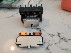
A Standard Relay's coil is supplied 24 VDC from the Power Center PCB via one of the two driver chips. When 24 VDC is received by the relay's coil wires, it closes the contacts that complete the circuit to turn on the equipment (i.e., power supplied to Line 1 goes out Load 1 to the equipment).
If a relay's coil wires are shorted, or an AC relay coil is plugged into a relay socket, when that circuit is activated, it will damage one of the two relay Driver Chips (Part No. 3814) on the Power Center PCB. These chips are socketed and can be replaced.
All of the newer relays used by Jandy, Hayward, Pentair are nominally 24vdc and are completely interchangeable. The one marketed for Hayward is half the price of the one that has Jandy on it on Amazon. Or look up this, by Omron, the company that likely makes them for all the companies mentioned (about $25.00) . The Omron brand was available at wholesale until the big three said they would pull their product if the wholesalers continued to offer them.[44]
- G7L-2A-BUBJ-CB-DC24
A member has tiny little black ants in his cabinet that caused his relays to constantly fail.[45]
The ants get squished in the contacts, which do not allow the contacts to make full contact and you get arcing which burns the contacts.
Relay Connector
Relay connectors are 2.5mm-pitch 2-pin female JST XH-style connector.[46]
Aqualink Temperature Sensor
There is only one model AquaLink RS temperature sensor used for all three sensor inputs. It is used for reading water, air and solar temperatures. The sensor is described as a 10K RTD (10,000 Ohms - Resistive Temperature Detector) sensor, although the actual resistance will vary with temperature.
The temperature sensor can be tested with a multimeter as described in Temperature Sensors.
When measuring resistance across the sensor leads you must remove the sensor from the circuit. Either disconnect both wires from the terminal bar or remove the terminal bar from the PCB. Then, to test the Sensor, “0” out your meter and take reading across the sensor.
If a sensor fails, the Controller display will scroll on that sensor “Shorted” (i.e., little or no resistance), or “Open” (i.e., no continuity).
Replacing the Aqualink Transformer
There are reports of replacement Aqualink transformers part #R0466400 have not had the proper 24VAC when connected to the board. There seems to be defective transformers in the supply chain. If you have the problem return the transformer as defective and get a replacement.[47]
Note that pool and spa rated transformers have "divorced windings" meaning there is no way for 120 volt current to contact the 24 volt side. Most typical transformers do not include this feature in the design meaning they can fail and send 120 volts down the low voltage wire. No doubt the Jandy transformers are expensive but make sure you get an exact equivelent or your risking your life.
4 Pin and 10 Pin Replacement Terminal Blocks
Jandy charges ridiculous prices for the red 4 screw and green 10 screw terminal blocks. They are called "Riacon" terminal blocks.
Metz part number 31007104, Digi-key part number 1849-1116-ND is the 4 pin block. These are black colored rather than the red colored ones, but otherwise they are the same.[48]
Metz part number 31007106 is the 6 pin block. Digi-Key Part Number 1849-1107-ND.
Metz part number 31007110 is the 10 pin block, Digi-Key Part Number 31007110-ND.[49]
Jandy Aqualink Cover Screws
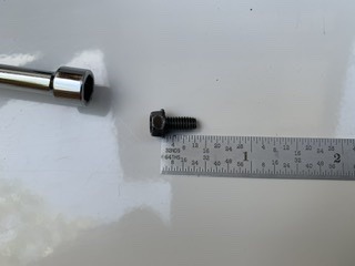
The screws holding the cover panel on the Aqualink are 8-32 x 3/8” long with a combination 1/4” hex and Phillips head.[50]
The screw holding the 9V battery cover plate in the old Aqualink panels is a 4-0 screw.[51]
Aquapure Display Garbled
Check the ribbon cable and reboot the system.
Aquapure not found. Check Aquapure RS485 and power connections
This is a common issue. The Aquapure is still running, it just disappears from the Aqualink.[52]
- Check the RS-485 two wire data line between the Aquapure board and the Aqualink for any corrosion or loose wires. Reseat the wires and tighten the screws.
- Try power-cycling the Aquapure panel. Turning the filter pump off then on again usually will accomplish this.
- "Clear Memory" on the web app
Aqualink Controlling Pentair Intelliflo Pump
Pentair_IntelliFlo_Pumps#Connecting_Pentair_IntelliFlo_Pump_to_Jandy_Aqualink
Aqualink Controlling Pentair UltraTemp Heat Pump
This thread described how a member connected a Pentair MasterTemp gas heater fireman's switch to the heater relay and the Pentair UltraTemp Heat Pump controls through the Aqualink SOLAR control.
For the Ultratemp heat pump you have to wire the Aqualink RS into thinking the Solar circuit is a Heat Pump.
Here's the process:
- Turn off the power.
- Flip Aqualink DIP switches S1-8 and S2-1 ON - this tells the app that there's no Solar, just Heat Pump.
- Connect the Mastertemp fireman switch on pins 1-2 of the 10 pin greenbar, pins 3-4 are for the Spa temp sensor, pins 5-6 are for the Pool temp sensor (optional since Heat Pump has temp sensor) and pins 7-8 are for the Air temp sensor
- Connect the 2-pin Solar Pump relay (24VDC) socket - lower right side of board, 3rd from right - to an unused AUX relay - or add a relay in the high-voltage area of the power center.
- Connect the pool/spa + common spade relay terminals on the Ultratemp control board to the LINE and LOAD screws of the HP control relay you connected to the SOLAR socket.
Now when you hit Solar pump on the Aqualink board, the heat pump will turn on. It shows up as Heat Pump in the app/web.
The Ultratemp Heat Pump control board spade connectors are expecting only a contact switch, no voltage - basically the same operation as the Mastertemp fireman switch, though none of this is documented. If you connect the 24VDC to the spade terminals directly, instead of to the relay, you may damage the Aqualink board - at best you'll blow the fuse on the back of the board.
Turn the power on and go into the app, and the Heat Pump should appear.
In this configuration, the Aqualink simply is a smart switch for the heat pump. All the temp ranges, heat/cool mode, etc. is still configured at the Ultratemp panel.
Aqualink Controlling Hayward Aquarite
In the early days of Aqualink versions Rev R and prior the Aqualink would control a Hayward Aquarite SWG as long as the system type in the Aquarite control panel was set to AL-5.[53] People say that Hayward seems to have stop supporting the AL-5 that permits the Aqua Rite to work with Aqualink.
With Rev T Jandy changed the code and an AL=5 set Aquarite identifies itself as "Aquapure", but the system recognizes it as "Aquarite (not compatible)"
In addition, as of Rev T there is code that if the Aqualink sees an non-compatible SWG, it will remember this and even the Jandy AquaPure will not work. So if you have powered up your Aqualink with the AquaRite or private label connected directly, you have locked out all SWGs. Replacing the CPU will not fix the lockout. The lockout is on the main board logic board, not the CPU which can be switched out.
You need to use the Chlorinator Translator in the communication cable between the Jandy Aqualink® RS and the Hayward®/GoldLine chlorinator to enable them to communicate with each other and prevent the lockout. Do not hook up the AquaRite to your iAqualink until the translator is in place for if you do, the iAqualink will lock out all SWCG even with the translator.
This allows the SWG generation % to be adjusted through the iAqualink app and separate SWG % set for the pool and spa modes.
Aqualink with a Cover-Pools Cover
Cover-Pools pool cover owners can control other pool features based on the position of their cover with Jandy AquaLink integration. When the cover is closed, AquaLink will deactivate any water features, limit chlorine output, and reduce pump runtime, saving up to 50% on energy and chemicals.[54]
By including a Cover-Pools Interface Board with a Jandy AquaLink control system, you gain the following functionality:
- One Touch controller shows whether the pool cover is open, closed, or partially open
- iAquaLink app shows whether the pool cover is open, closed, or partially open
- Salt chlorine production levels automatically adjust when the cover is opened or closed
- Water features, booster pump cleaners, and pool lights will automatically shut off when the cover is closed
- Pump runtime automatically decreases when the cover is closed.
Aqualink Clock Losing Hours Through The Day
Replace the CR2032 battery on the board.
How to erase color light assignment on Jandy RS panel?
How do you un-assign an AUX relay from being a color light on a Jandy RS-8 panel? System setup only seems to allow assigning a color light but not clearing it. "Clear memory" doesn't do it.
Apparently un-assigning a color light can only be accomplished with a Jandy One Touch panel. Download the AquaLink RS Simulator (AquaLink_RS_Simulator.EXE) from the Jandy site, install in on a laptop, plug a RS485 dongle attached to the Jandy into the laptop, and then you can to unassign the AUXes using the OneTouch PC app.[55]
Aqualink All Button Control Panel All LEDs Are On
See page 17 in Jandy Aqualink Troubleshooting Manual.
The microprocessor was hit by a power surge. Turn off all power to the system. (If the PCB is prior to Revision N, disconnect the nine (9) volt battery.) Wait two (2) minutes and then turn the power on. If this frees up the system, you will need to reset the time and date, except with a Revision N board. Programming will not be lost. It is advisable to install a Surge Protection Kit
See Section 5. Troubleshooting on page 32 of Jandy Aqualink RS Installation Manual.[56]
| Symptom | Problem | Possible Solution |
|---|---|---|
| All LEDs are on at the control panel and the part # and revision letter of the control panel software are displayed. The override switches at the power center operate as they should. | Control panel is not communicating with the power center PCB. | Check the two center wires (black & yellow) of the four conductor cable. Also check the installation of the CPU Board on the power center PCB. If the PPD is not seated correctly the system will not communicate. |
| All LEDs are on at the control panel and the part # and revision letter are displayed, but override switches at the power center do not operate at all. | 1. Damaged or improperly installed CPU Board.
2. Damaged power center PCB. |
1. Check alignment of the CPU Board. 2. If CPU Board is installed correctly, replace the power center PCB. |
If the PCB is damaged BP Engineering, Inc. may be able to repair it.
There have also been times when the hidden LEDs have stayed lit. Cycling the power as described above has sometimes cleared it.
Aqualink PDA stuck on "waiting"
"Waiting" on your PDA means the PDA is trying to establish a connection between the PDA controller and the Jbox antenna. Check to make sure there is no damage to the antenna.[57]
If there is none, first, you'll want to try changing the channels on the controller. To do this, hold the up and down arrow on the controller for 5 seconds. You'll see the display show you the number channel you're currently on. At this point, use a screwdriver to open up the jbox. You should leave it connected to the Aqualink RS power center. Once you have it open, flip the switch entitled "LEARN" to the ON position, then press the reset button. You should see some blinking inside the jbox. Change the channel on the controller using the up and down arrows. Any channel will do. Once this is done, you'll see the light inside the jbox turn solid. Turn "LEARN" to the off position, and hit the reset button inside the jbox. This will reset the connection.
If this does not work for you, turn the power off completely to your power center at the breakers. Open your power center and flip down the front board. On the back of this board you'll have a 9v or CR2032 battery. Replace this with a new battery. Make sure that when you pull the existing battery out, you allow a minimum of 30 seconds to pass before putting a new battery inside. Close the power center and turn power back on.
If the issue persists, you may have a failed front board, the RS485 connection can be bad on either end, the wires can be bad, etc. Typically, changing the channel and/or replacing the battery will resolve the issue.
The red light on the J-box is a power light. You're getting the required 8-10vdc from the board. It can then be an issue with continuity, or the battery as previously mentioned. I would suggest replacing this battery. Which type you have can be determined by turning the power off completely to the power center and flipping the front board down to access the battery on the back of the front board.
If you're unable to get to the channel change screen on the PDA, you may have an issue with the buttons. They may not be making contact with the PCB due to debris. It is unlikely that the board itself failed if you're able to see "WAITING FOR CONNECTION" to begin with.
Jandy Aqualink JI-x000
The Jandy Aqualink JI-x000 series came out before the "RS" style Aqualink that we've had since the late 90s. You're likely going to have a lot of trouble finding any repair parts for this system - it has to be nearly 30 years old at this point.[58]
Jandy did/does sell a conversion kit for the JI and first-generation AquaLink to make them a modern RS system if you wanted to go that route.
After the conversion from JI to RS the cabinet will look like this:[59]
.
- ↑ https://www.iaqualink.com/-/media/zodiac/global/downloads/0748-91071/6594.pdf?
- ↑ https://www.iaqualink.com/-/media/zodiac/global/downloads/h/h0433600.pdf
- ↑ https://www.troublefreepool.com/threads/ugh-jandy-pda-ps8-on-new-build.228353/post-2145421
- ↑ https://www.troublefreepool.com/threads/jandy-aqualink-rs4-or-rs8.223919/post-2147754
- ↑ https://www.troublefreepool.com/threads/trying-to-figure-out-my-jandy-vsp-pump.299073/post-2616142
- ↑ https://www.troublefreepool.com/threads/can-you-program-a-pentair-intelliflo-with-aqualink-rs-all-button.248740/post-2182370
- ↑ https://www.troublefreepool.com/threads/iaqualink-schedule-help.241373/#post-2115318
- ↑ https://www.troublefreepool.com/threads/adding-vs-pump-to-aux-1-2-3-in-iaqualink.248733/post-2193099
- ↑ https://www.troublefreepool.com/threads/century-connect-automation-support-for-vgreen-evo.279984/#post-2454153
- ↑ https://www.troublefreepool.com/threads/need-help-pentair-11056-iaqualink-communication-issues.270642/post-2372572
- ↑ https://www.jandy.com/-/media/zodiac/global/downloads/0748-91071/6594.pdf?force=1
- ↑ https://www.troublefreepool.com/threads/jandy-flopro-vs-2-7-pump-replacement-options.264938/post-2320766
- ↑ https://www.troublefreepool.com/threads/need-help-with-figuring-out-pool-automation.192362/post-1695405
- ↑ https://www.troublefreepool.com/threads/pumps-turns-off-after-clean-mode-cycle.284628/post-2494563
- ↑ https://www.jandy.com/-/media/zodiac/global/downloads/0748-91071/6594.pdf?force=1
- ↑ https://www.troublefreepool.com/threads/adding-additional-jva-to-iaqualink.248026/post-2172907
- ↑ https://www.troublefreepool.com/threads/how-to-check-aqualink-rs-solar-temp.267913/post-2346552
- ↑ https://www.troublefreepool.com/threads/automation-and-jva-value-setup-recommendations.309155/post-2704181
- ↑ https://www.troublefreepool.com/threads/4-wire-vs-2-wire-jandy-heater-to-iaqualink.229677/post-2014304
- ↑ https://www.troublefreepool.com/threads/jandy-epump-help-troubleshooting-and-testing.224804/post-1983288
- ↑ https://www.troublefreepool.com/threads/replacing-two-single-speed-pumps-with-variable-speed-pumps-maybe-new-electronics.233363/post-2063945
- ↑ https://www.jandy.com/-/media/zodiac/global/downloads/sl/sl6458.pdf?force=1
- ↑ https://www.iaqualink.com/-/media/zodiac/global/downloads/h/h0435500.pdf?force=1
- ↑ https://www.zodiacpoolsystems.com/-/media/Zodiac/Global/Downloads/H/H0365300
- ↑ https://www.troublefreepool.com/threads/replacing-two-single-speed-pumps-with-variable-speed-pumps-maybe-new-electronics.233363/post-2064046
- ↑ https://www.troublefreepool.com/threads/replacement-antenna-for-iaqualink-2-0.222411/post-1948660
- ↑ https://www.troublefreepool.com/threads/iaqualink-antenna.229224/post-2011335
- ↑ https://www.troublefreepool.com/threads/iaqualink-iq-900-antenna-replacement.198391/post-2333020
- ↑ https://www.troublefreepool.com/threads/iaqualink-problems-eero-mesh.219583/post-1922162
- ↑ https://www.troublefreepool.com/threads/iaqualink-cant-connect-to-my-wifi-network.199377/post-2306131
- ↑ https://www.troublefreepool.com/threads/connection-issues-with-aqualink-2-0-and-eero-mesh-network.287214/post-2518506
- ↑ https://www.troublefreepool.com/attachments/aqualink_rs-pdf.615082/
- ↑ https://repairalmostanything.com/thread/944/repairing-jandy-rs6-pool-controller
- ↑ https://www.troublefreepool.com/threads/smart-alexa-spa-remote-jandy-8-emulates-jandy-8-button-spa-remote.248854/
- ↑ https://www.jandy.com/-/media/zodiac/global/downloads/h/h0572800.pdf?force=1
- ↑ https://www.jandy.com/-/media/zodiac/global/downloads/h/h0574200.pdf?force=1
- ↑ https://www.troublefreepool.com/threads/aqualink-systems.194033/post-1710216
- ↑ https://www.jandy.com/en/products/controls/aqualink-upgrade-and-conversion-kits
- ↑ https://www.troublefreepool.com/threads/jandy-aqualink-ppd-cpu-revisions.87511/
- ↑ https://www.troublefreepool.com/threads/iaqualink-brand-new-equipment-how-to-upgrade-to-rev-r.167497/post-1477668
- ↑ https://www.troublefreepool.com/threads/jandy-infinite-watercolors-coming-soon.275866/post-2503168
- ↑ https://www.troublefreepool.com/threads/iaqualink-with-in-floor-cleaning-system.299530/page-2#post-2624323
- ↑ https://www.tcpoolequipment.com/pool-equipment-store/pc/Jandy-AquaLink-RS-3-15-AMP-Fuse-6658-p10802.htm
- ↑ https://www.troublefreepool.com/threads/automation-what-input-voltage-and-current-to-drive-jandy-relay.262047/post-2291846
- ↑ https://www.troublefreepool.com/threads/jandy-zodiac-power-center-board-w-cpu-burning-out-relays.263863/post-2316568
- ↑ https://www.pololu.com/product/1164
- ↑ https://www.troublefreepool.com/threads/iaqualink-and-transformer.200163/#post-1766850
- ↑ https://www.troublefreepool.com/threads/compatible-10-pin-terminal-pluggable-bar-zodiac-6610-for-zodiac-aqualink-rs.258207/post-2256932
- ↑ https://www.troublefreepool.com/threads/compatible-10-pin-terminal-pluggable-bar-zodiac-6610-for-zodiac-aqualink-rs.258207/post-2256888
- ↑ https://www.troublefreepool.com/threads/jandy-power-center-screws.233446/post-2045104
- ↑ https://www.troublefreepool.com/threads/aqualink-pda-battery-screw-size.299970/post-2626038
- ↑ https://www.troublefreepool.com/threads/jandy-swg-confusion.249981/#post-2190415
- ↑ https://www.troublefreepool.com/threads/aqualink-wont-recognize-aquarite.84727/
- ↑ https://www.coverpools.com/pool-professional/components-and-technology/aqualink-automation/
- ↑ https://www.troublefreepool.com/threads/how-to-erase-color-light-assignment-on-jandy-rs-panel.231792/post-2030439
- ↑ https://www.troublefreepool.com/threads/aqualink-rs8-all-lights-on-no-control-over-equipment.213972/
- ↑ https://www.troublefreepool.com/threads/aqualink-pda-stuck-on-waiting.52573/post-443923
- ↑ https://www.troublefreepool.com/threads/fuse-burst-on-jandy-aqualink-automation.260715/#post-2280178
- ↑ https://www.troublefreepool.com/threads/iaqualink-upgrade.270183/#post-2368242


