Introduction: This was originally just a collection of notes for myself regarding tidbits of information I've discovered while trying to reprogram the Aqualink panel at my new home. However, I think it may be useful to other weary travelers with similar issues who find their way here via Google.
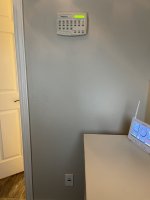
Long story short, the previous homeowner lost the PDA/handheld so I had absolutely no way to set the time/date, change programming, etc. Everything had to be done manually through the outdoor panel in either Service or Time Out mode. In fact, the last owner was told by a pool installer that there was nothing they could do to reprogram a system without the handheld (I'm assuming this is because their Service Controller would not talk to the panel, more on that later). This led them to paying an electrician to install an external mechanical manual freeze controller since they couldn't access the settings in the Aqualink. On top of that, since the 9v backup battery went dead and the time setting was lost, the system was turning on/off at all hours of the day and night. The former homeowner told me he was effectively just controlling the panel manually all the time in Service mode. This was clearly going to drive me bananas.
Why would I want/need to do this?: I'm a big fan of just because you can (as mentioned in another thread), but this would be a useful solution for someone who has a broken or missing PDA (like me), has a defective Aqualink Touch controller, has a defective OneTouch controller, or has a defective All-Button controller. Zodiac/Jandy has decided that the unwashed masses of the public are not allowed to even buy their hardware, and must work through backlogged, sometimes incompetent pool builders and other "authorized sources". I am a firm believer that *I* should be able to do whatever I want post-purchase, and I'm entirely indifferent to what Jandy thinks. And while I am sympathetic to pool companies needing to make money, I'm not plunking down thousands of dollars to have someone come out and install/replace what is effectively 1990s-era basic automation technology.
What do I need?: Up front for basic requirements, you will need a PC with Windows (or a Windows virtual machine on another OS), the free Aqualink Simulator software, a cheapo RS-485 USB to Serial adapter, and a small length of wire - CAT5e/6 works great. Beyond those basic requirements, what else you need depends on what equipment you currently have:
Any AquaLink RS panel with a firmware revision BEFORE Rev I: You're a bit out of luck. Revision I was the first Aqualink firmware to support the OneTouch and All-Button controllers and likely this will NOT work with your setup. Either find a 44-pin PPD with Revision I or greater and swap it, or use this time to upgrade your panel to something new. Rev I came out in 5/2000, so I can't imagine there's much of this old stuff still floating around.
Aqualink RS with an existing PDA/J-box setup: You will need to first confirm whether or not you have conventional firmware. Conventional firmware has a revision code such as Q, MMM, T.2, etc. PDA-only PPDs and CPUs will have a label stating that they are PDA, for example "REV. PDA 1.2" or "PDA PSx COMBO Rev 7.1".
Contrary to what Jandy's "helpful" tech support told me, AL Touch, OneTouch and All-Button controllers are NOT compatible with the PDA-only firmware. For a time, Jandy sold PDA-only PCBs - these units were sold at a discount since you got purposely neutered functionality. You will need to move to conventional non-PDA firmware by swapping the PPD or CPU (depending on your board revision). Since my PCB was the 52-pin socket style with PDA firmware installed, and I have a pool and spa setup, I bought a 52-pin Revision K Pool+Spa non-PDA PPD off eBay for $20 and swapped it in. (Edit: I've since bought a new-style "PDA" PCB on eBay open box. These go super cheap because nobody wants the PDA board. I then bought a "broken" PCB that had a CPU daughtercard with T.2 firmware attached. I swapped the CPU daughtercard onto the open box PCB and I was off to the the races with the latest firmware). You can find a list of firmware revisions through 2012 here.
Aqualink RS with an existing Aqualink Touch, OneTouch or All-Button controller: You're good to go with the basic requirements above.
Aqualink RS with no PDA, OneTouch or All-Button, but you've confirmed the firmware revision is Rev I or NEWER: You should be good to go with the basic requirements above.
How do I get started?: First, download and install the Aqualink Simulator software. While this particular group of applications is very poorly documented (read: not at all), we can deduce that it has at least two functions: It can simulate an entire Aqualink RS setup complete with a virtualized Power Center, and it can directly control physical Aqualink hardware with the right interconnects. Why you would want to simulate an Aqualink setup on your PC is beyond my grasp of human psychology and the scope of this document. What's interesting to us is the physical hardware control part. Once the software is installed, navigate to the folder (typically this will be ~/Program Files (x86)/Alwin32). You will find a bunch of stuff in here, but we're really only concerned with PCInt, which we'll come back to later.
Next, we'll need to physically connect your computer to the Aqualink PCB. Remove the protective front panel from your Power Center. Use common sense here - there is a lot of voltage in this box, so don't mess around in the bottom of the panel - the high-voltage section. If you touch it, you may die, and it will hurt the entire time you're dying. Just turn off ALL the power at the panel before messing around in here. Look at the top left hand corner of your PCB. You will find 1 or 2 4-pin RED connectors (depending on PCB revision - 44/52-pin socketed PPD boards have 1 connector, CPU boards have 2 plus an RJ-11 receptacle). This connector may already have wires running into it, especially if you have an existing PDA, AL Touch, OneTouch, or All-Button controller. If you don't have any of these things, and there are still wires attached here, you should probably trace them back and figure out where they go before you start messing with it. They could be part of a variable speed pump, chlorine generator, etc. If you have a totally open connector, just use that:
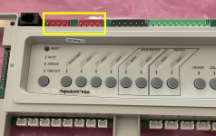
There should be a 4-pin terminal block (Jandy calls it a "terminal bar") clipped onto one of these connectors. If there isn't, you can buy them on fleabay or scamazon. I need to dig through the Mauser catalog to see if I can find a generic cheap version, because the $15-20 the official Jandy ones go for is nuts for a 2 cent plastic block. These blocks sure look close to the real thing, but the keying is ever-so slightly different. You may be able to Dremel it out a bit if someone wants to take a $1 gamble.
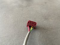
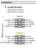
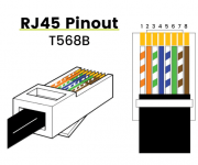
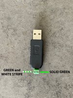
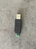
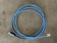
Take your length of CAT5 and strip it and clean up one of the pairs and fold the rest out of the way. For me, I put the striped wire on pin 2 and the solid color on pin 3. Do not connect anything to pin 1 or 4 as these are power. On your USB-to-serial adapter, connect the striped wire to the D+ terminal and the solid color wire to D-. Now, make sure the drivers are installed for your RS-485 adapter. When you plug it into your PC, it should show up under the "Ports (COM & LPT)" category in Device Manager. If it does not, you will need to install the drivers manually. I'm using an old Windows 7 x64 laptop that I use for automotive tuning, and I found drivers that work here. EDIT: Hey, dfwnoob from the future here. There are more pictures/details as far as wiring goes in the post below.
Once you've confirmed your RS-485 adapter is working properly, you can go ahead power up the Aqualink panel and launch the PCInt.exe application in the Aqualink Simulator folder on your PC. When the application opens, you'll see that it looks just like an All-Button controller. Neat! On first launch, the application will try to scan your COM ports to find the Aqualink system. If it does, great! In the Setup menu, under RS System Model, select the version that most closely matches your system. Assuming everything is talking and happy, you will see this:
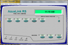
You should see the normal messages, time, temperature, model, etc. scroll across the "screen". Pressing the buttons on the virtual controller should actually activate/deactivate your real pool hardware. If the screen says "WAITING" or "No Communication" for more than a few seconds, something is not communicating properly. Ensure your drivers are installed correctly and ensure your wiring is right (heck, try switching it around on one side, maybe you/I made an error somewhere). To attempt to re-connect, click Setup and then Comm Port. This will run through the port scan again. With the PCInt application working, you can now control your Aqualink system the same way an All-Button controller does. You can go into the menu and set/review programming, options, etc. No need for an expensive service call, and no need to spend hundreds of dollars on a new controller just to set the time/date and adjust your programming.
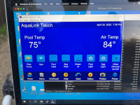
If you're used to the Aqualink Touch experience, use the TLsim.exe application (requires firwmare Revision Q or later):
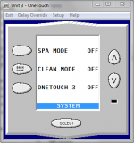
If you're a sadomasochist and prefer the painful experience of the OneTouch panel or PDA, you can use Onetouch.exe/PDA.exe and get that, too:
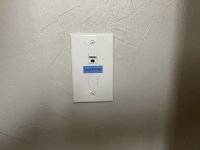
So, there you go. I tried to make the most thorough guide for anyone wanting/needing the virtual controller software. I hope this helps someone down the road who ends up in the same boat as me. I'm strongly considering running a length of CAT5 from the panel outside to my office and just putting a normal RJ45 jack in the wall so I can plug in and adjust the system whenever I need to from the comfort of my desk. This board has been IMMENSELY helpful for me as a new pool owner and hopefully this guide helps someone else, too.
Long story short, the previous homeowner lost the PDA/handheld so I had absolutely no way to set the time/date, change programming, etc. Everything had to be done manually through the outdoor panel in either Service or Time Out mode. In fact, the last owner was told by a pool installer that there was nothing they could do to reprogram a system without the handheld (I'm assuming this is because their Service Controller would not talk to the panel, more on that later). This led them to paying an electrician to install an external mechanical manual freeze controller since they couldn't access the settings in the Aqualink. On top of that, since the 9v backup battery went dead and the time setting was lost, the system was turning on/off at all hours of the day and night. The former homeowner told me he was effectively just controlling the panel manually all the time in Service mode. This was clearly going to drive me bananas.
Why would I want/need to do this?: I'm a big fan of just because you can (as mentioned in another thread), but this would be a useful solution for someone who has a broken or missing PDA (like me), has a defective Aqualink Touch controller, has a defective OneTouch controller, or has a defective All-Button controller. Zodiac/Jandy has decided that the unwashed masses of the public are not allowed to even buy their hardware, and must work through backlogged, sometimes incompetent pool builders and other "authorized sources". I am a firm believer that *I* should be able to do whatever I want post-purchase, and I'm entirely indifferent to what Jandy thinks. And while I am sympathetic to pool companies needing to make money, I'm not plunking down thousands of dollars to have someone come out and install/replace what is effectively 1990s-era basic automation technology.
What do I need?: Up front for basic requirements, you will need a PC with Windows (or a Windows virtual machine on another OS), the free Aqualink Simulator software, a cheapo RS-485 USB to Serial adapter, and a small length of wire - CAT5e/6 works great. Beyond those basic requirements, what else you need depends on what equipment you currently have:
Any AquaLink RS panel with a firmware revision BEFORE Rev I: You're a bit out of luck. Revision I was the first Aqualink firmware to support the OneTouch and All-Button controllers and likely this will NOT work with your setup. Either find a 44-pin PPD with Revision I or greater and swap it, or use this time to upgrade your panel to something new. Rev I came out in 5/2000, so I can't imagine there's much of this old stuff still floating around.
Aqualink RS with an existing PDA/J-box setup: You will need to first confirm whether or not you have conventional firmware. Conventional firmware has a revision code such as Q, MMM, T.2, etc. PDA-only PPDs and CPUs will have a label stating that they are PDA, for example "REV. PDA 1.2" or "PDA PSx COMBO Rev 7.1".
Contrary to what Jandy's "helpful" tech support told me, AL Touch, OneTouch and All-Button controllers are NOT compatible with the PDA-only firmware. For a time, Jandy sold PDA-only PCBs - these units were sold at a discount since you got purposely neutered functionality. You will need to move to conventional non-PDA firmware by swapping the PPD or CPU (depending on your board revision). Since my PCB was the 52-pin socket style with PDA firmware installed, and I have a pool and spa setup, I bought a 52-pin Revision K Pool+Spa non-PDA PPD off eBay for $20 and swapped it in. (Edit: I've since bought a new-style "PDA" PCB on eBay open box. These go super cheap because nobody wants the PDA board. I then bought a "broken" PCB that had a CPU daughtercard with T.2 firmware attached. I swapped the CPU daughtercard onto the open box PCB and I was off to the the races with the latest firmware). You can find a list of firmware revisions through 2012 here.
Aqualink RS with an existing Aqualink Touch, OneTouch or All-Button controller: You're good to go with the basic requirements above.
Aqualink RS with no PDA, OneTouch or All-Button, but you've confirmed the firmware revision is Rev I or NEWER: You should be good to go with the basic requirements above.
How do I get started?: First, download and install the Aqualink Simulator software. While this particular group of applications is very poorly documented (read: not at all), we can deduce that it has at least two functions: It can simulate an entire Aqualink RS setup complete with a virtualized Power Center, and it can directly control physical Aqualink hardware with the right interconnects. Why you would want to simulate an Aqualink setup on your PC is beyond my grasp of human psychology and the scope of this document. What's interesting to us is the physical hardware control part. Once the software is installed, navigate to the folder (typically this will be ~/Program Files (x86)/Alwin32). You will find a bunch of stuff in here, but we're really only concerned with PCInt, which we'll come back to later.
Next, we'll need to physically connect your computer to the Aqualink PCB. Remove the protective front panel from your Power Center. Use common sense here - there is a lot of voltage in this box, so don't mess around in the bottom of the panel - the high-voltage section. If you touch it, you may die, and it will hurt the entire time you're dying. Just turn off ALL the power at the panel before messing around in here. Look at the top left hand corner of your PCB. You will find 1 or 2 4-pin RED connectors (depending on PCB revision - 44/52-pin socketed PPD boards have 1 connector, CPU boards have 2 plus an RJ-11 receptacle). This connector may already have wires running into it, especially if you have an existing PDA, AL Touch, OneTouch, or All-Button controller. If you don't have any of these things, and there are still wires attached here, you should probably trace them back and figure out where they go before you start messing with it. They could be part of a variable speed pump, chlorine generator, etc. If you have a totally open connector, just use that:

There should be a 4-pin terminal block (Jandy calls it a "terminal bar") clipped onto one of these connectors. If there isn't, you can buy them on fleabay or scamazon. I need to dig through the Mauser catalog to see if I can find a generic cheap version, because the $15-20 the official Jandy ones go for is nuts for a 2 cent plastic block. These blocks sure look close to the real thing, but the keying is ever-so slightly different. You may be able to Dremel it out a bit if someone wants to take a $1 gamble.
Take your length of CAT5 and strip it and clean up one of the pairs and fold the rest out of the way. For me, I put the striped wire on pin 2 and the solid color on pin 3. Do not connect anything to pin 1 or 4 as these are power. On your USB-to-serial adapter, connect the striped wire to the D+ terminal and the solid color wire to D-. Now, make sure the drivers are installed for your RS-485 adapter. When you plug it into your PC, it should show up under the "Ports (COM & LPT)" category in Device Manager. If it does not, you will need to install the drivers manually. I'm using an old Windows 7 x64 laptop that I use for automotive tuning, and I found drivers that work here. EDIT: Hey, dfwnoob from the future here. There are more pictures/details as far as wiring goes in the post below.
Once you've confirmed your RS-485 adapter is working properly, you can go ahead power up the Aqualink panel and launch the PCInt.exe application in the Aqualink Simulator folder on your PC. When the application opens, you'll see that it looks just like an All-Button controller. Neat! On first launch, the application will try to scan your COM ports to find the Aqualink system. If it does, great! In the Setup menu, under RS System Model, select the version that most closely matches your system. Assuming everything is talking and happy, you will see this:

You should see the normal messages, time, temperature, model, etc. scroll across the "screen". Pressing the buttons on the virtual controller should actually activate/deactivate your real pool hardware. If the screen says "WAITING" or "No Communication" for more than a few seconds, something is not communicating properly. Ensure your drivers are installed correctly and ensure your wiring is right (heck, try switching it around on one side, maybe you/I made an error somewhere). To attempt to re-connect, click Setup and then Comm Port. This will run through the port scan again. With the PCInt application working, you can now control your Aqualink system the same way an All-Button controller does. You can go into the menu and set/review programming, options, etc. No need for an expensive service call, and no need to spend hundreds of dollars on a new controller just to set the time/date and adjust your programming.
If you're used to the Aqualink Touch experience, use the TLsim.exe application (requires firwmare Revision Q or later):

If you're a sadomasochist and prefer the painful experience of the OneTouch panel or PDA, you can use Onetouch.exe/PDA.exe and get that, too:

So, there you go. I tried to make the most thorough guide for anyone wanting/needing the virtual controller software. I hope this helps someone down the road who ends up in the same boat as me. I'm strongly considering running a length of CAT5 from the panel outside to my office and just putting a normal RJ45 jack in the wall so I can plug in and adjust the system whenever I need to from the comfort of my desk. This board has been IMMENSELY helpful for me as a new pool owner and hopefully this guide helps someone else, too.
Last edited:


