TX Pool

Bronze Supporter
Nov 29, 2022
49
TX
Surface
Vinyl
Chlorine
Salt Water Generator
SWG Type
Pentair Intellichlor IC-60
My current pool filter pump needs replaced. It is an old Pentair whisper flo two speed pump that was controlled with a standard control panel with Intermatic timers. The pool also has a single speed Polaris booster pump that runs a Polaris suction pool cleaner. The wiring was not done well and the breakers from the main house panel are not done correctly to the existing panel and it is not easy to isolate the power from the pool equipment.

I am thinking about purchasing the new 011533 WhisperFlo VST Variable Speed Pool Pump and Pentair EasyTouch 4P 520591 controller and running a new single power cable over from the main breaker panel so the pumps and heater are all on their own circuits with breakers for disconnect.

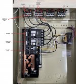
I have read through both installation manuals for the pump and the control panel and also some general information on the web and this form that did include photos inside the box. Are there any wiring diagrams that show how to wire the relays in the panel from the breakers to the relay and from the relay to the pump?

I understand I need the control cable for speed control on the filter pump, but it is just not 100% clear yet on the relay wiring. Is it really just as straight forward as line - line from the breaker to the relay and then line - line from the relay to the pump? Do you have to interconnect anything on the relays for the booster pump or is that interlock to run for the booster done in the programming for filter pump run times and booster pump run time? I understand how to do all of the wiring and I am comfortable with that I just did not want to mix up anything on the relays.

Also will the control panel take the place of the old thermostat freeze protection? My understanding is the new control panel uses the air and water temperature probes and can call the filter pump to run and heater to run for freeze protection. I have a Pentair heater that I will also wire to the control panel.

Thanks in advance! Just want to make sure not missing anything major as I am looking at this control panel upgrade.
 
Tx,

VS pumps are not wired to a relay... They get constant AC power directly from the breaker.

The automation tells the pump when to run and at what speed via an RS-485 cable.

You might want to look at the new IntelliFlo3..

Thanks,

Jim R.
 
Tx,

Freeze protect is controlled by the air temp and will turn on anything that you configure to turn on when freeze protect turns on.

You will have to connect the AC power for your booster pump to an Aux relay. It is just as simple as you assumed. Line to line and load to load. Just think of a relay as a wall switch in your house, only instead of using your hand to turn the switch on and off, the automation does it for you. If you can wire a wall switch, you can wire a relay.

The automation will tell the booster when to run based upon your programming.

All you need to do is have the main pump running to prevent a pool from freezing, you do not need to turn on the heater.

You might want to get ScreenLogic, which allows you to use your PC or phone to control the EasyTouch. It also makes programming about 10 x easier to do and understand.

Thanks,

Jim R.
 
Last edited:
Sorry for the slow response to the information above! I have taken some time to review all of the information above and some additional posts that I found on this forum that talked about similar issues and I think I understand the path forward.

1. Thanks for the suggestion on the Intelliflo 3; maybe next time I will get that as I cannot get for a reasonable price in my area and already have the control panel.

2. WhisperFlo VST
2A. Wire the new WhisperFlo VST from the pump motor to a breaker in the control panel. (line - line - GD)
2B. Wire the RS-485 cable from the port on the pump and connect the yellow and green wires to Ports 2 & 3 on the J7 terminal on the COM Port in the panel
2C. Program pump on the local controls to the pump.
2D. Program the pump on the Easy Touch control panel and/or through Screen Logic if installed
2E. Pump follows program from control panel first and if that is not working or communicating the pump will run of the drive programmed info.

3. Booster Pump
3A. Run power from another breaker in the control panel to an AUX relay (line - line - GD)
3B. Run power from the AUX relay to the Booster Pump (line - line - GD)
3C. Program easy touch to turn on and off the booster pump to run the cleaning system.
Question - in the program is there an interlock that only allows this booster pump to run when the Filter pump is also running? I have not found this part in the manual yet but I am assuming it is out there.

4. Heater (looking at Pentair MasterTemp Hat Gas but have not firmed up)
4A. Run power from the heater to a breaker in the control panel (line - Neu - GD) .
4B. Follow instruction in manual, but in general connect two-conductor cable from heater controller to the J19 terminals in the Easy Touch Panel for the gas heater
4C. If desired a heater bypass valve can be installed can be wired to the heater for bypass of the heater when not in use (do not have the manual with me today but saw the instructions mentioned were you can wire into the heater control panel and run to the Inteallavalve actuator and the heater will control the bypass valve)
4D. Turn on / off and set heater temp from local heater controls or from the Easy Touch Control Panel. (Is this same as the pump and the Easy Touch will govern?)

5. MISC
5A. Wire and install wireless control panel if desired to control Easy Touch system from inside
5B. Wire and install screen logic if desired to control Easy Touch system from phone or computer with internet access

I know I have to figure out on my own, as each install has its own unique situations, but if you see something that looks like I am getting too far off of the rails I would be grateful for a bump to get headed back in the right direction.

I hope I am not crazy for biting this off, but this forum seems to have a ton of good information along with some good videos on the web! I have a firm understanding of electrical and plumbing so I general I have "done" the wiring and "done" the plumbing just not for these systems. I am going to leave the gas piping to a plumber and set the heater and wire up but have them make the final connection, something about the gas that makes me a little nervous. We landed at a place with a pool but the equipment is original and has not been maintained. The pool itself is in good shape just the ancillary systems need a little care. IF all goes well I will add my new equipment to my signature and I have no doubt I will be back to talk all about pool chemistry and the rest of the system maintained once we get back into pool season. I am shooting to wire and plumb everything in early spring and have been slowly planning the work and looking to get stuff on order.
 
2. WhisperFlo VST
2A. Wire the new WhisperFlo VST from the pump motor to a breaker in the control panel. (line - line - GD)
2B. Wire the RS-485 cable from the port on the pump and connect the yellow and green wires to Ports 2 & 3 on the J7 terminal on the COM Port in the panel
2C. Program pump on the local controls to the pump.
2D. Program the pump on the Easy Touch control panel and/or through Screen Logic if installed
2E. Pump follows program from control panel first and if that is not working or communicating the pump will run of the drive programmed info.

All pumps, gas heater and lights need to be on GFCI CBs. Use a Pentair PA220GF or Siemens CB (QF220AP) for the VS pump.


Will you have a SWG? If so you want the SWG connected to the same CB as the pump.

Better to wire your 20AMP 240V GFCI CB for your filter pump to the LINE side of the filter/pump relay.

Then connect your pump power wires to the LINE side screws of the filter/pump relay and a SWG will connect to the LOAD screws of the filter/pump relay.

3. Booster Pump
3A. Run power from another breaker in the control panel to an AUX relay (line - line - GD)
3B. Run power from the AUX relay to the Booster Pump (line - line - GD)
3C. Program easy touch to turn on and off the booster pump to run the cleaning system.

Breaker is wired to the AUX relay LINE screws. Pump is wired to the LOAD screws.
Question - in the program is there an interlock that only allows this booster pump to run when the Filter pump is also running? I have not found this part in the manual yet but I am assuming it is out there.

In the EasyTouch configuration you tell it that AUX has a booster pump and the ET will only power it when the filter/pump is running.

4. Heater (looking at Pentair MasterTemp Hat Gas but have not firmed up)
4A. Run power from the heater to a breaker in the control panel (line - Neu - GD) .

I would run the heater at 240V and connect it to the same breaker as your booster pump at the LINE screws of the AUX relay. Or you can power it from the LOAD screws of your filter/pump relay.
4B. Follow instruction in manual, but in general connect two-conductor cable from heater controller to the J19 terminals in the Easy Touch Panel for the gas heater

Correct. That is the "Firemans switch" connection.


4C. If desired a heater bypass valve can be installed can be wired to the heater for bypass of the heater when not in use (do not have the manual with me today but saw the instructions mentioned were you can wire into the heater control panel and run to the Inteallavalve actuator and the heater will control the bypass valve)

See Heater Bypass - Further Reading


4D. Turn on / off and set heater temp from local heater controls or from the Easy Touch Control Panel. (Is this same as the pump and the Easy Touch will govern?)

You set the local heater control panel to 104F in SPA mode once and then don't touch it. The EasyTouch does all the temperature control of the heater.

5. MISC
5A. Wire and install wireless control panel if desired to control Easy Touch system from inside
5B. Wire and install screen logic if desired to control Easy Touch system from phone or computer with internet access

ScreenLogic is highly recommended for EasyTouch systems.

I hope I am not crazy for biting this off, but this forum seems to have a ton of good information along with some good videos on the web! I have a firm understanding of electrical and plumbing so I general I have "done" the wiring and "done" the plumbing just not for these systems. I am going to leave the gas piping to a plumber and set the heater and wire up but have them make the final connection, something about the gas that makes me a little nervous. We landed at a place with a pool but the equipment is original and has not been maintained.

It sounds like you have a good understanding of the work. It just takes some planning to have all the materials. I did a similar project with an IntelliCenter. My thread on it is at....


I installed all the breakers and wired the breakers to the AUX relays on my workbench. Do as much prep work as you can on the cabinet before mounting it on the wall. Figure out what knockouts you will be using for conduit from each device and what your wire path will be. If you are installing a 120V GFCI convenience outlet in the lower right of the panel you can prewire that. You can connect your 120V pool lights to the LOAD side of the GFCI outlet.

Post pics of your prewired panel and some of us will do a QC review on the work. Use this thread and keep us informed of your progress and any questions along the way.
 
  • Like
Reactions: HermanTX
@ajw22 thanks for the information above! I will take a look at it and let you know if I have any questions. I will for sure post some pics along the way once I get started of progress and if I run into any other questions along the way.
 
@ajw22 I am finally getting close to wiring up the panel and will have to post some pictures. I have been upgrading the house electrical and getting a new cable ran over to the panel and trying to get all of the attic work done in the cold weather.

I did have one quick question for you on the panel; there is the transformer that is integral to the panel and I was not sure if that needed its own GFCI breaker or if you can connect it with one of the other breakers on the bus for the booster pump. I had not chased this in the manual yet and just thought I would ask if you had any thoughts.

TIA
Andrew
 
there is the transformer that is integral to the panel and I was not sure if that needed its own GFCI breaker

No, the panel power does not require a GFCI.

or if you can connect it with one of the other breakers on the bus for the booster pump.

You can share a breaker with a pump and the panel but you should not.

If the pump trips a shared breaker your panel will go dark and you will lose all pool controls. It will become difficult diagnosing the problem.

Best to have a dedicated breaker for the panel so your system stays up even if your devices have problems.
 

Enjoying this content?

Support TFP with a donation.

Give Support
So I am a little new to pool ownership and I have a lot going on for the spring pool season. As we were closing the pool last year the filter pump and timer died and I am in the process of replacing the filter pump and control panel and have gotten tons of help from this site in other threads that address those items. Durning this conversion I have also decided to go the route of a SWG and not sure the chlorine puck feeder that is current installed on the piping. Following is my question around the SWG and the pool opening in the spring.

1. Any thoughts on opening the pool myself vs paying to have it opend?
2. I looked at the closing invoice and they did add antifreeze to the pipes and I am assuming that will need some extra steps?
3. If I have the pool company open or if I try myself should I get it up and running on chlorine pucks first and then add the salt to the water to start the process of converting to the SWG?
4. I just ordered my test kit from TFTtestKits and got the SWG options; is this the best way to test and see if enough salt has been added?
5. Any other threads or tips on SWG install, startup, or pooling opening would be appreciated!
 
Will you have a SWG? If so you want the SWG connected to the same CB as the pump.

Better to wire your 20AMP 240V GFCI CB for your filter pump to the LINE side of the filter/pump relay.

Then connect your pump power wires to the LINE side screws of the filter/pump relay and a SWG will connect to the LOAD screws of the filter/pump re
So I did bite the bullet and after doing more research and reading I get the SWG since I am changing everything else I figured why not. I am assuming you wire the Filter Pump and SWG this way as the pump does not need controlled by the relay since it is variable speed and is controlled by the pump or automation system but you want the SWG wires to the load side so it can only run when the filter pump is running.

In this setup do you have to set the controller to “turn on” the relay when the filter pump is running? Since the filter pump does not need the relay to close to run I was not sure how you forced the system to still close the relay so the SWG gets power.

I am starting to prewire the panel and will send some photos once I get things moving in the next few weeks.
 
The EasyTouch is smart enough to turn the filter pump relay on and off anytime it turns the VS pump on and off via RS-485 commands.
 
  • Like
Reactions: TX Pool
.1. Any thoughts on opening the pool myself vs paying to have it opend?

Depends what needs to be done?

You have a safety cover on it? Can you handle the weight and folding of the cover?

2. I looked at the closing invoice and they did add antifreeze to the pipes and I am assuming that will need some extra steps?

You can vacuum out the antifreeze or let it mix with the pool water and chlorine will break it down.
They use RV antifreeze.

3. If I have the pool company open or if I try myself should I get it up and running on chlorine pucks first and then add the salt to the water to start the process of converting to the SWG?

No, use liquid chlorine to initially chlorinate your pool. Then if the water temp is over 55F add your salt and after 24 hours to dissolve turn on the SWG.


4. I just ordered my test kit from TFTtestKits and got the SWG options; is this the best way to test and see if enough salt has been added?

Yes.
5. Any other threads or tips on SWG install, startup, or pooling opening would be appreciated!
What SWG are we discussing?
 
Depends what needs to be done?

You have a safety cover on it? Can you handle the weight and folding of the cover?


You can vacuum out the antifreeze or let it mix with the pool water and chlorine will break it down.
They use RV antifreeze.


No, use liquid chlorine to initially chlorinate your pool. Then if the water temp is over 55F add your salt and after 24 hours to dissolve turn on the SWG.


Yes.

What SWG are we discussing?
Pentair Intellichlor IC60
 
Set the IC60 to 0% so it is off before you add salt. There is no easy way to power off the cell.

Add 2/3 of the salt PoolMath says you need. Brush any salt that lands on the pool floor around to dissolve it. Run your pump for 24 hours to dissolve and distribute the salt. Then test the salinity using your test kit. If you are not to 3000 ppm then add some more salt.

The IC60 will run with 2800 ppm and more. Optimum salt level is 3600 ppm. Over 4000 ppm will show the HIGH SALT LED.

Once you get salt to 3000ppm or above then turn on your SWG by increasing the %.

How many gallons in your pool?

What is your daily pump runtime?
 
Last edited:
Be sure to test the salt content BEFORE adding any salt. You might be surprised at how much salt is already in the pool water.
 
@ajw22 I have wired up the power wires and marked the future power connections in the photo below. Can you take a quick look and let me know if you have any comments or suggestions? When I wire the SWG in this manor I would assume the relay closes when the control system knows the filter pump is running based on the control wire that will be added.

I will take another photo of the control wires and will send a similar photo once I get those marked up.
 

Attachments

  • Control Panel Wire.jpg
    Control Panel Wire.jpg
    470.4 KB · Views: 31
Do you have pool lights? You need a 120V GFCI CB for lights?

Will you install a convenience GFCI outlet on the lower right of the panel?

The control panel did not need to be 240V. I would have used a 120V CB for the control panel power. That gives you another slot for a 120V pool light CB.

Heater should be connected to the LOAD side of the filter/pump relay so it does not run if the pump is not running.

You should install a Surge Protection Device connected to a 20A 240V CB in the loweest slot of the panel - Electrical Surge Protection - Further Reading

control-panel-wire-jpg.475905
 

Enjoying this content?

Support TFP with a donation.

Give Support
Thread Status
Hello , This thread has been inactive for over 60 days. New postings here are unlikely to be seen or responded to by other members. For better visibility, consider Starting A New Thread.