Do you have pool lights? You need a 120V GFCI CB for lights?

The pool light is out of commission as it had a leak and needs replaced. It was an older(?) style 12 V that had a transformer that is also shot. It was one of those old ones that had a color wheel in the light and water got into the housing and does not work anymore. I am not sure if I will replace with a new 120 V light or a 12 V light as I will have to wait until I can get into the pool and see what kind of light would fit into the existing housing in the pool. There are still some open spots in the control panel that I can wire a new light or a transformer to once I get to the light.

Will you install a convenience GFCI outlet on the lower right of the panel?

I am not sure; there are other outlets outside in the area and was not sure if I needed to add another one to the panel.

The control panel did not need to be 240V. I would have used a 120V CB for the control panel power. That gives you another slot for a 120V pool light CB.

I had this breaker already and just used it but agree can replace and just use 120 if I get tight on slots in the future.

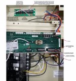
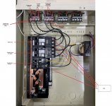
Heater should be connected to the LOAD side of the filter/pump relay so it does not run if the pump is not running.

Ok; so wire it to the load side same as the SWG so it can only run when the pump is running.
You should install a Surge Protection Device connected to a 20A 240V CB in the loweest slot of the panel - Electrical Surge Protection - Further Reading
Noted - I will read and get this added to the panel. Did you use a panel mounted one or something like the FirstSurge? I have used a FirstSurge before on our main panel and it seems this is the best and more safe option for this panel associated with the pool and since it is located outside.

Did you also use any of the RS-485 isolators on those control cables or just the power supply? I did not see any options for the communications cables and only the RS-485 style communications.

Thanks for the suggestions!! If I have any other power questions I will post and I will get another picture posted on the control wires when I get to that point.

See photo for revised on the heater power location and addition of the SPD.
 

Attachments

  • Power Revised.jpg
    Power Revised.jpg
    455.9 KB · Views: 7
Last edited:
@ajw22 here is my stab at the control wiring for the following items:
1. WhisperFlo VST Filter Pump
2. MasterTemp Heater
3. Air Temp Sensor
4. Water Temp Sensor
5. IntelliChlor SWG
6. Screen Logic Remote Module
7. Easy Touch Remote Screen Module

Also do you recommend putting an SPD on the control wires? If so which ones?
 

Attachments

  • Control Panel Control Wire.jpg
    Control Panel Control Wire.jpg
    541.3 KB · Views: 11
Last edited:
I don’t think an EasyTouch supports RS-485 communication with the MasterTemp connected heater. You just use the 2 wire Firemans Switch.
 
Ok so I am making some progress. I think this is one of the largest projects I have tackled in a long time but worth it. Still a ways to go but feel like I can see the finish in the distance.

I was going to do the auto bypass on my heater but worried I do not have enough room. The AC unit is there and I cannot get the heater moved to get more room. I am not sure if a manual bypass would save some space. I need to get the check valve, bypass, and SWG in-line and at most have six linear feet unless I go vertical.
 

Attachments

  • 5CAFCE8B-1E5D-4E01-813B-700803B2BF2D.jpeg
    5CAFCE8B-1E5D-4E01-813B-700803B2BF2D.jpeg
    599.8 KB · Views: 9
@ajw22 have you installed the 2 wire connections from the easy touch to the master temp heater for the fireman’s switch? The picture is the jumper from the fuse to the fireman connection and I am assuming you pull that jumper and run the two wire to the relay in the east touch panel. Since easy touch cannot control the the heater is there any real reason to run this wire?
 

Attachments

  • BB583532-619D-4EF9-AC77-7A7B196D2588.jpeg
    BB583532-619D-4EF9-AC77-7A7B196D2588.jpeg
    352.1 KB · Views: 1
The picture is the jumper from the fuse to the fireman connection and I am assuming you pull that jumper and run the two wire to the relay in the east touch panel.

Correct.


The MasterTemp Installation Manual specifies to use 18 gauge wire with a minimum 3/64” (1.2mm) thick insulation rated for a temperature rise of at least 105°C. The area the wire passes through can get hot and melt wire insulation.

EasyTouch Control System: Insert the conductors into the GAS HEATER two-screw terminals (J19) on the motherboard.

Since easy touch cannot control the the heater is there any real reason to run this wire?

The EasyTouch can control a MasterTemp heater using the "firemans switch'. The ET cannot use the RS-485 connection for control.
 
Has anyone used the RS-485 isolators that is referenced on the additional reading for surge suppression? Since they are only two pin I am assuming you only use them on the RS-485 cable from the pump to the control board. Anyone use anything on the four wire controls from the SWG, remote devices, and other four wire connections that connect to the communication ports on the panel?
 
I am not sure; there are other outlets outside in the area and was not sure if I needed to add another one to the panel.
I would install the convenience outlet, then you can use the load side of that gfci to power your lights once installed. The gfci outlet is cheaper than a gfci breaker.
I was going to do the auto bypass on my heater but worried I do not have enough room
Your pad is massive compared to what my pb left me so you have plenty of room for the heater bypass. Automated vs non automated uses the same components and space. The pump wattage difference bypassing the heater vs not bypassing, at the same flow, is significant.
 
  • Like
Reactions: TX Pool
Thread Status
Hello , This thread has been inactive for over 60 days. New postings here are unlikely to be seen or responded to by other members. For better visibility, consider Starting A New Thread.