Main Drain to Skimmer Valve Ratio

M,

The labels do not look right to me either.. :scratch:

It would be pretty stupid to plumb two skimmers together on the same line at the equipment pad..

As a test, I suggest that you turn the handle of the pipe marked "skimmers" so that it points straight up.. In theory, this should shut off both skimmers.. Then go look at each skimmer and see if they are working or not..

Please tell us what you find.

Thanks,

Jim R.
  • Like
Reactions: PoolStored

Difficulty measuring pH

I noticed recently that when I measure the pH using the kit my pool builder gave me, I get different results than using the tf-pro. Using the pool builder's kit, which uses a chlorine neutralizer prior to the pH test solution, the pH looks pretty good. I'd say 7.7 or 7.8. Using the tf-pro, it looks more concerning, like 8.1 I think. It's hard to read though because the scale is so light. I just recently bought a refill for the tf-pro, so the chemicals are fresh. Leslie's seems to agree with the pool builder's kit, saying it's only 7.7 or so. Am I doing anything wrong in the testing?

Levels:
pH 7.7-8.1?
Chlorine: 16
TA: 80
Salt: 4200
Calcium: 775
CYA: 90
Borates: 40

Thank you!

pool builder.jpgtf-pro.jpg

tf-pro.jpg

pool builder.jpg

Anyone using a solar powered skimmer?

I love my Betta SE Plus. Not gimmicky. Does a great job clearing small floaties and helps to keep the skimmer clear. Pushes stuff off the sides and in areas of weak circulation.

This is a good thread. I opted for the 3 year warranty for some piece of mind.

  • Like
Reactions: Dan-H

1740844333401.jpeg

1740844048827.png

1740843933976.png

Intellicenter not following Pool schedule, when Spa is being used during schedule end time

It only happens to me when I turn on the spa while the pool is scheduled and on, and the pool schedule ends while the spa is on. When the spa turns off (either manually or when its egg timer expires), the pool resumes but after its scheduled end time so it never turns off. Manual override and manual heat are also both disabled on my system, maybe this is related.

All the other scenarios mentioned do work correctly.

1740843779712.png

1740843715159.png

1740843690263.png

Pentair Intellicenter firmware 3.002

I finally took the plunge and updated to 3.002 yesterday. Some comments below.

The multi expansion panel bug that reared its head in 2.026 is gone :)

Most of the other bugs that appeared in 2.006 and 2.017 appear to have been fixed.

Integration with Control4 via the official driver was a little scary and required two reboots of the IntelliCenter and one reboot of Control4 to start working properly but has been rock solid for 24 hours now.

I haven’t tested multiple IntelliBrite lights yet to see if the problems (with large numbers of such lights over multiple panels) from v1 and v2 are still present as I converted these to generic lights in Pentair a few weeks ago (as reported elsewhere) and moved the colour control from Pentair to Control4 to get stability.
I noticed this a few days later. At first glance it looked to be working fine with temps and status of circuits showing in C4 but I couldn’t turn my SPA on a few days later until I rebooted Director.

Not getting power to Mastertemp400

The control panel on my Pentair Mastertemp400 heater has stopped getting power. I’ve read other post trying to fix this myself, but I’m at a point where I don’t know what to check next. Any guidance would be much appreciated.

My system is about 15 years old and it’s a Pentair Easytouch control panel connected to a Mastertemp400 heater. We use the heater several times a week and it has been working fine for the last couple of years. I know that I have to have the spa on for the heater to get power. When I press the ‘spa’ button I no longer see “HEATER” displayed on my easy touch control panel and no lights light up on the heaters control panel.

Here is what I’ve done so far:

I checked the voltages on the heater and I’m getting 220VAC input and 28VAC out of the transformer. I checked the plugs to the control board and the 4-pin connector at J7 has 28VAC and the 5-pin connector at J1 has 0VAC (brd_vac.jpg attached). At this point I thought the control board was bad so I replaced it. The issue remained. Still no power. Next, I checked the wire between the easytouch control panel (J19) and the heaters firemans switch. I used a multimeter with audible continuity and verified that each screw post on J19 had continuity to the firemans switch post and they were not shorted together (fsw.jpg attached). What do I check next? I’m out of ideas.

Thanks,
-Mike
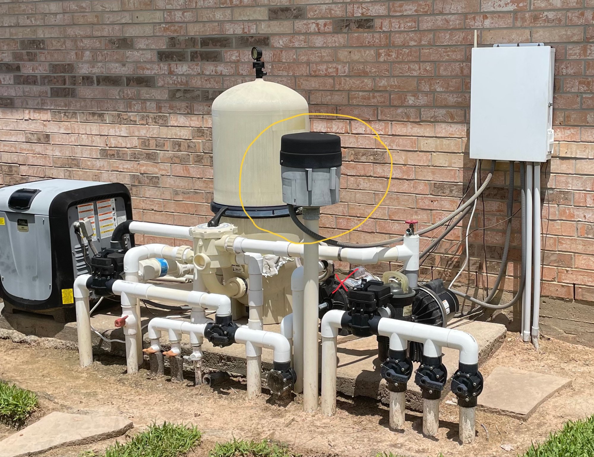
I forgot to mention the fuse by the firemans switch is not blown.
Thanks,
Mike

Main Drain to Skimmer Valve Ratio

Do you have two skimmers?
Interesting you have two pipes marked as Main Drain. Usually, even though you may have two drain covers on the pool floor, they are plumbed together and only one pipe for main drain is at the equipmemt pad.

Usually the valves should be set to pull at least 70% (or more) from the skimmers to maximize skimming the pool surfafe and capturing debris before it settles to the pool floor. For a pool without an IFCS, probably 80%-90% skimmer would work best.

Brand New Max e Therm burning through igniters literally

The purple dots are the 24 VDC coil.

When the power input is 240 volts, the ignitor is powered by S1/240 and S2/FS instead of S1/120 and S2/FS.

This is changed by the voltage selector plug (Red or Black).

The Voltage Selector Plug also changes the Blower Windings from Series (For 240 Volts) to Parallel (For 120 Volts).

The Voltage Selector Plug also changes the System Transformer Windings from Series (For 240 Volts) to Parallel (For 120 Volts).

1740841321690.png

Manufacturer: SANYOU

Manufacturer part number: SMI-S-224L

Type of relay: electromagnetic

Contacts configuration: DPDT

Rated coil voltage: 24V DC

Contact current max: 8A

1740841952984.png

1740841964076.png

1740842128709.png

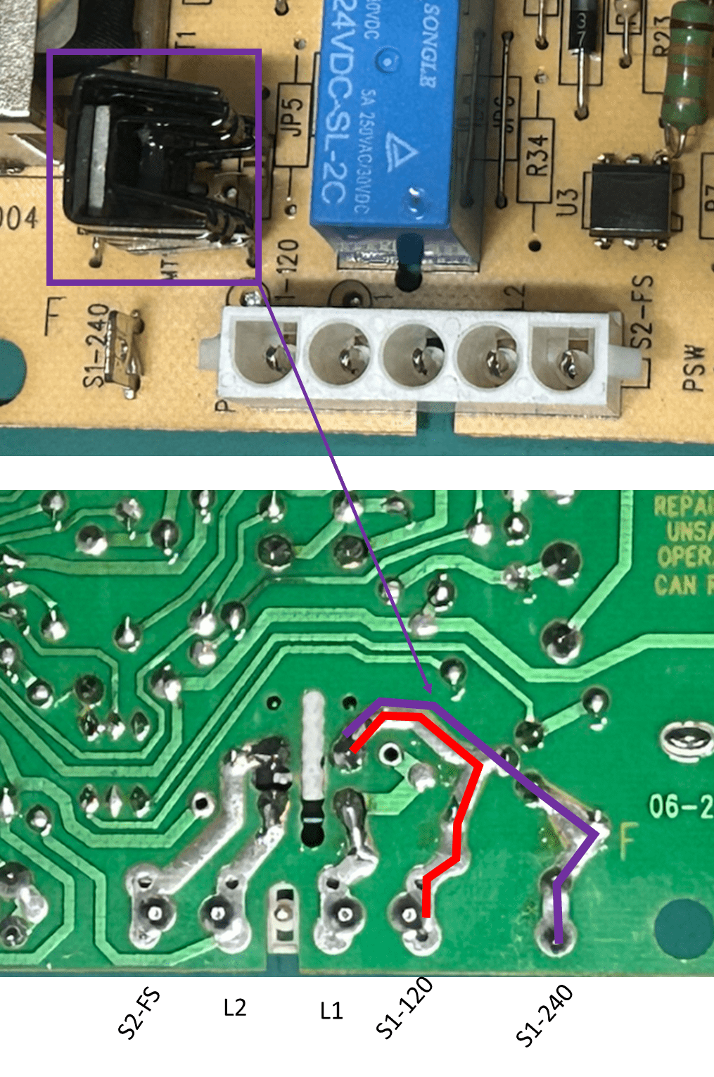
When the heater is operating (connected to) in 240Vac, the IC MT1 (in purple box) is switching the input L1 to get 120Vrms in the ignitor. The picture diagram shows the L1 circuit route: a) red (110V direct) and b) purple (240V switching by MT1).

1740842720086.png
1740851236638.png

Attachments

  • 1740842158108.png
    1740842158108.png
    591 KB · Views: 0
  • Like
Reactions: Hulaomr

1740842720086.png

1740842158108.png

1740842128709.png

1740841964076.png

1740841952984.png

1740841321690.png

Screenshot_20250301-092108.png

Screenshot_20250301-092119.png

Filter