Pentair ic40, surge board, intelliph and swg transformer.

It’s hard to tell but it looks like in the bottom left a little chips might be burned
Same chips that blew on my surgeon board. Right near d3 and d4. That’s why it’s not communicating with the ic40. Replacing the surge board fixed it. I can change the ic40 and it reports salt level back to the app.
 
  • Like
Reactions: slickrock22
oh nooos... D3 and D4 are dead on this surge board too. if one or both died "short", they will interrupt communication between the salt cell and the easytouch. (i'm assuming the small gauge 4-conductor cable on the terminal block in the lower left of your photo goes back to the easytouch, and the thicker wires in the top left go to the salt cell?)

assuming the comm chips on the salt cell are OK... i think your easytouch and salt cell will be able to talk again if you remove d3 and d4. if you have a multimeter, you can use the continuity or resistance function to check if they're shorted - or you can just skip all that and remove them because they're clearly dead.

to remove d3/d4, you can either unsolder them or very carefully cut/file/grind/snip the plastic with whatever you've got on hand - being careful not to damage the copper traces on the board until each side of the part is no longer connected to the other (you don't have to get it all off). then clean it up with the highest concentrated isopropyl alcohol you've got.
Boards went out to you yesterday. You should have them tomorrow.
 
  • Like
Reactions: ogdento
J9 input to the surge board is also overheated, even if you change the board i would definitely cut and crimp a new connector just to start fresh. You do need a new board.
This is what i did in case you are interested. Even if pentair gives you a new board and iph i would not connect them like that again.

So is this an issue with the power feeding the surge board exceeding the capacity of the board? Should there be some type of power limiting device (fuse?) on the wire going into J9?
 
My current running theory…I run my ic40 at 60%. I generally run it for 8 hours per day during the summer. Since I had just shocked the pool and was opening it I kept the pool running for 24 hours. I do this every year when I open the pool. After thinking about it for a bit, it would make sense that it was an heat/amperage issue given that I ran it for 24 hours (which it rarely does) and some time during that 24 hours it blew. Or none of it makes sense tbh

I’ll say this much from now on I’m turning the ic40 to zero when I run the pump for 24 hrs.
 
thanks @Latitude22 ... i forgot yours were still coming!
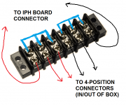
hey @Dirk, on oakwater's unit i'm going to pull the connector, relay and the other dead parts so I can look at the board and try to figure out a little more. I was thinking I'd use wire nuts or a basic "barrier terminal block" or something to keep high currents off the board...

The terminal block idea was to cut the wires off of the connector, attach the 2 red wires coming into the box, and 1 of the red wires from the connector to 3 of the terminals, joining them with a 3-position jumper. Then do the same for the black wires. The red/black wires going to the iph board will occupy one of the un-burned connector positions ;) That should be fine because it doesn't take much to power the iph board itself... something like this:
iph_rewire.png
I don't really think it's any better that just wire-nutting them together... so maybe just do what's easiest? Either way you do it I'm sure it'll void any remaning warranty. But it might be something you just have to do when you install an intellichlor or iph?

Oh, and I'll leave the white/green (data lines) on the connector because they don't seem to cook... which makes sense because there shouldn't be any current on them anyway. What doesn't make sense is how the data line protection diodes and comm chips are blowing up when there shouldn't be any current.
 
So is this an issue with the power feeding the surge board exceeding the capacity of the board? Should there be some type of power limiting device (fuse?) on the wire going into J9?
Not really. The J9 connector if not mistaken comes from the fuse and the IC transformer. In most cases the fuse is not blowing. My reasoning is that the connector on the iph is not rated properly for the current draw. My first idea was to bypass the red/black in/out on the iph for an XT60 connector, but then power would not be cut when dosing acid, so it defeated the purpose.
but does J9 go to a bridge rectifier on the other side of the board?
Probably on the back of the surge board, the surge board inputs AC that comes directly from the IC transformer via Fuse.
 
My original thinking is that i should isolate the IC power from anything that could hurt it electronically. The IC is more expensive than the IPH board and harder to get at this particular time.
 
When I google Pentair 521593 (The part # on my Surge Board) I get results for 521218. Is that the correct replacement board? Looks like it has been redesigned and I do not see d3/d4. Maybe they resolved the surge board failure?
I stumbled on this just now. I've never seen it before. Perhaps it might help. It calls for 521091, so there might be several versions. Might be worth a call to Pentair tech support. If you do call, ask them if they've addressed this burned connector issue on either the surge board or the IntellipH circuit board.

 
Last edited:
My first idea was to bypass the red/black in/out on the iph for an XT60 connector, but then power would not be cut when dosing acid, so it defeated the purpose.
I'm not following the posts about the resistors, etc. Just wanted to clarify: the IpH doesn't cut power to the IC while it's dosing. The IC stays powered up the whole time. The IpH sends some sort of "0% Output" command to the IC, which stops any chlorine production, then the IpH doses, then restores the IC's output setting to its previous state. You can see that happening on the IC's output LEDs. That's why the IC can resume its production cycle immediately after acid dosing without having to go through its initial power-up/startup mode (where the LEDs flash for about five minutes).
 
thanks @Latitude22 ... i forgot yours were still coming!
hey @Dirk, on oakwater's unit i'm going to pull the connector, relay and the other dead parts so I can look at the board and try to figure out a little more. I was thinking I'd use wire nuts or a basic "barrier terminal block" or something to keep high currents off the board...

The terminal block idea was to cut the wires off of the connector, attach the 2 red wires coming into the box, and 1 of the red wires from the connector to 3 of the terminals, joining them with a 3-position jumper. Then do the same for the black wires. The red/black wires going to the iph board will occupy one of the un-burned connector positions ;) That should be fine because it doesn't take much to power the iph board itself... something like this:
View attachment 402650
I don't really think it's any better that just wire-nutting them together... so maybe just do what's easiest? Either way you do it I'm sure it'll void any remaning warranty. But it might be something you just have to do when you install an intellichlor or iph?

Oh, and I'll leave the white/green (data lines) on the connector because they don't seem to cook... which makes sense because there shouldn't be any current on them anyway. What doesn't make sense is how the data line protection diodes and comm chips are blowing up when there shouldn't be any current.
Yes, the terminal block would be good, connecting the red to red and black to black before they get to the board, then powering the board with a third set of red and black. That's exactly what I was hoping for. I probably would just solder everything together, because that eliminates potential corrosion issues, but that's tomato/tomahto.

But here's the rub, and what I was hoping you could discover for us. I'm pretty sure the two black wires are connected together via traces on the board, so connecting them together before they get to the board should be fine. That would solve for the cases where the black pins in the connector were charing. What I couldn't determine is if the two red wires are similarly, directly connected together on the board, or if those two traces run off somewhere else on the board and have something else between them (some other component). If which case connecting them together before they get to the board would circumvent some function.

As I just wrote, I know the circuitry does not cut power to IC during dosing, so it's not that. Are you able to see/confirm how the traces from the two black pins are connected on the board? That looks to me to be the ground bus for the board. And can you see how the traces that connect to the two red pins don't seem to be connected together on the board in the same way? That's where I got stuck. Where do they run off to?

And you're right, why are the comm components burning, because they should not be subjected to the same current that is running in the red/black combo? It doesn't look to be caused by the heat being generated by the pins inside the connector, does it?

I was hoping, between all the "stock pile" coming our way, we could maybe get a franken-board working, power it up, and then experiment? Someone just volunteered to send you another one (but maybe that was a surge board, I'm losing track).
 

Enjoying this content?

Support TFP with a donation.

Give Support
My current running theory…I run my ic40 at 60%. I generally run it for 8 hours per day during the summer. Since I had just shocked the pool and was opening it I kept the pool running for 24 hours. I do this every year when I open the pool. After thinking about it for a bit, it would make sense that it was an heat/amperage issue given that I ran it for 24 hours (which it rarely does) and some time during that 24 hours it blew. Or none of it makes sense tbh

I’ll say this much from now on I’m turning the ic40 to zero when I run the pump for 24 hrs.
That might have been it. Just FYI, in case you didn't know: a 60% setting doesn't mean the IC is producing chlorine at 60% capacity, or 60% power, it means it's producing at 100% capacity/power for 60% of the time. I think the cycle is 5 minutes long. So with a 60% output setting, it's going full blast (full power) for three minutes, then shuts down (zero power) for 2 minutes, then 3, then 2, like that.

But your theory is still possible, as maybe things "cooled off" just enough in that 2 minute off period. Running 100% would have eliminated any cool down.
 
hey @Dirk... sorry I left out that detail before... the only ones that are separated are the data lines, which are connected to the dpdt relay. so the reds are connected together on the board, as are the black wires. not a great design... larger cells can draw 7.5 amps? (maybe more??) and there are certainly connectors rated for that, but if you're running the pool a lot there's gonna be heat, and it's in a harsh environment... so why use that kind of connector at all!? i just don't get their design choice.

@rstrouse describes the relay and comms operation in that other post we were looking at...

the simplest thing would be to skip the iph altogether... but I want to see 1. if i can get this dead iph working again and 2. make it work with an aquarite! i recently setup nodejs-poolController which should let me intercept and/or spoof commands to maybe turn my aquarite swg cell on/off while the iph is dosing
OK, well that is especially good news. I may wait until you get that board working, connect the red and black before the board, and confirm that's going to work, but if so, I'm going to solder my red and black together within the IpH controller. Excellent work! Thank you.

You gotta check this out. This is from yet another thread that has overcurrent problems. His fuse is popping (yah, another one!) and his IpH board is showing the signs (black pin). But check out his surge board! Looks like Pentair is working on this! Both the pic he provided and in the video he linked. The connector is gone!! They're solving this the same way Felipe and I did, at least on the surge boards. Maybe they'll do this for the IpH? They're probably reading these threads. They're probably watching me type this!!! :rolleyes:

Of course, he's still got breaker problems. Something must be happening in the SWG itself, like I described earlier. Pulling too much current. Not just it's normal, expected too-much-current, but some manufacturing defect that's making things even worse.

 
Last edited:
@slickrock22, note the post above. Looks like Pentair has eliminated the trouble connector on the surge board. So that means for new models the cable and board are now one (not individually replaceable, as they were). That's not to say you can't still get those older parts, just pointing out that might explain, in part, all the model numbers flying around. As I said, best to call Pentair and make sure you get the right replacement. Or, you might see if they sell the new board with soldered cable and replace both, and upgrade your setup in that way. (I would! Why buy another board with the same faulty connector?)
 
Oh shoot. I jumped the gun there. I was focussing on the pic the OP had posted. If you look at the video, you can see there is still a connector, but it's no longer on the board. It's on some short wires, and then the cable connects there. Interesting. Hopefully the new connector is of better quality. But if you replace just your old board with that new model, you're still going to have the old cable, which has the old pins, so what does that now mean? That's assuming the old cable fits into the new connector. Again, maybe replace both and hope for the best? Personally, I'd buy both, wait out the warranty, then cut out that connector and solder the wires together.
 
I stumbled on this just now. I've never seen it before. Perhaps it might help. It calls for 521091, so there might be several versions. Might be worth a call to Pentair tech support. If you do call, ask them if they've addressed this burned connector issue on either the surge board or the IntellipH circuit board.

I spoke with them today and referenced this post to understand that this is not an isolated issue. I hope that was ok.
 
I spoke with them today and referenced this post to understand that this is not an isolated issue. I hope that was ok.
Sure, it's a public forum. I would be surprised if they haven't already found it, or some other thread here about this problem. They need to solve for the surge boards and for the IntellipH controller boards, for all models of the IntelliChlor, it's not just the IC60. In fact, Pentair, if you're listening, it'd be great if you could post something that assures all of us that you're working on this. We have other manufacturers that post on the TFP forum, and it's great public relations for them when they do. Hint, hint!
 
  • Like
Reactions: slickrock22
hey @Dirk the surge board in that post looks like the same one @Latitude22 sent me.

i think you're talking about J9... the through-hole spade terminal... they could have just used those on the iph for the red/black wires (and not the surface mount ones they've got on the intellibrites, which tear off with the slightest force!!)
 
So maybe that's the new model?

Yah, spade connectors, sure. Of they could do something like they did on my surge card (which came out of the stand-alone Power Center for IC). They could have soldered the cable assembly directly to the board, with the other end, the jack, mounted in the case (where it would connect to the cables running to/from the EasyTouch and IC). I wish they had solved the surge board the same way: board and cable assembly as one.

They have to solve for the current. But they should also consider the environment. They need a certain amount of connections to make installation and repair simple, but they also need to eliminate as many connectors as possible to minimize potential corrosion issues. This stuff is outside, in the sun and wind and rain and heat and cold, and there's chlorine and acid and salts flying around...
 
Last edited:
  • Like
Reactions: ogdento
Just wanted to clarify: the IpH doesn't cut power to the IC while it's dosing. The IC stays powered up the whole time. The IpH sends some sort of "0% Output" command to the IC, which stops any chlorine production, then the IpH doses, then restores the IC's output setting to its previous state
Voltage does not cause the problem, its the time Current/amps flowing to the IC that burns the connectors. By now you know, we know, that i know, that everybody knows, how it works.
Thinking Think GIF by The official GIPHY Page for Davis Schulz


Now thinking back in time i used to run the cell 100% for the least amount of pump run time(when the toasting occurred). Now i run 20% for 12 hrs a day. So the time high current is flowing through the connectors on the iph(without cooling/rest) would be significantly higher. Just food for thought. Maybe we should recommend new users 24/7 pump run time with low % on the ICs, as a lesser fire hazard. :scratch:
 

Enjoying this content?

Support TFP with a donation.

Give Support