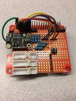
Arduino Solution for Failed Pentair Intelliph

JackthesE

Member
Jul 15, 2021
12
Orange County, CA
I just experienced a failure of a Pentair Intelliph (acid dispenser) control board, and I plan on replacing it with a home-brewed "Arduino" microcontroller-based board. Two diodes, D3 and D4 appeared fried on the native board. I don't know their function, but they may be supplying DC power to the pump motor, which will not run using "mandatory" commanding from the native board. The board led status is constant red. The pump motor runs fine when I supply it with 24 v DC, so I know it's the board that has somehow failed. The IC40 is making chlorine. The plumbing is fine, but I may replace the pump tube, just in case.
I place Arduino in quotes above, because I'm actually going to use an ESP32 microcontroller which is WiFi connected to the internet, and I will use the Arduino IDE (Integrated Development Environment) to program the microcontroller board. Basically, I'll design a unit that wakes up when power is supplied by the mother Pentair control panel, and then times the events. I'll start a recurring programmable timer to dispense a programmable amount of acid, just like the factory board. I'll shut off the IC40 chlorinator during the dispense, just like the native control board. I'll keep a record of the dispense times and amounts, and display it on a "dashboard" accessible from the internet. The amount of acid to dispense will be controlled from the internet dashboard. as well.
So, does anyone out there know of any other requirements I should include? Anyone know what the red, black, white and green wires in the connector are used for? I'll figure it out, but if someone can give me a head start, I would appreciate it. Any other Arduino enthusiasts out there that wants to contribute? Thanks...Jack Ripper.
 
Welcome to the forum!

I have no input but let's see if some other members might have some ideas.
 
Jack…this discussion is related, but not necessarily 100% relevant to what you are doing. Should be a fun project…

 
  • Like
Reactions: MyAZPool
So I measured the DC voltages from the panel, and the black wire is ground, the red wire is 26v and the other two wires appear to be a data bus of some sort, perhaps a I2C or a 485. The acid pump motor is a DC motor (has visible brushes) and a label that said 24 volts, and as I said above, when I hooked it up to the red and black wire it ran fine and pumped acid. So, as a temporary convenience I installed a double throw toggle switch on the side of the control box, and wired it so the chlorinator ran in one switch position (with the acid pump off) and the acid pump ran in the other switch position (with the chlorinator off). This allows me to use the acid in the Intelliph holding tank. I'm calling this Phase 1.

The specific wiring is as follows, with input meaning the wires coming from the main panel, and outputs meaning wires going to the chlorinator and acid pump:
(1) Inputs White and Yellow connected to Outputs to chlorinator White and Yellow (restores the data bus from chlorinator to main panel).
(2) Input Black connected to Outputs acid pump Black and chlorinator Black
(2) Input Red to center connector of the toggle switch (common).
(3) One side of the toggle switch to Output chlorinator Red.
(4) Other side to the toggle switch to Output acid pump Red.

With this configuration the chlorinator reports its status correctly to the main panel (salt level and flow switch position) under the Diagnostics>>Intellichlor menu item.

For the Arduino part, I'm using and ESP32 Dev Kit ($7), a buck converter voltage regulator ($3) and two relays ($3 each). These were the Amazon prices when I bought these items a while back. The buck converter drops the 26v to 5v, needed to run the ESP32 and the relay coils. The logic lines of an ESP32 actually run at 3.3V and that's produced within the Dev Kit board automatically. One relay will power the acid pump, and the other will power the chlorinator. I've mocked this up on a prototype board and it's running as expected. Next step is to go to soldered connections and tweak the software a bit.
 
@JackthesE
Last year around this time, I did quite a bit of digging to try to find out just how the IntellipH operated. Not because my ipH had failed but I was dissatisfied with the limitations of the ipH and so that started me on my journey to where I'm at now.

1. Yes, the green and white wires are connected to the IntelliClor via RS-485, however the ipH appears to only listen on the bus and does not transmit or send out any packets.
2. Apparently, the ipH is listening on the bus for certain packets transmitted by the IntelliChlor.
3. It's thought that those packets that it is listening for, are ones that indicate that the IntelliChlor is operating normally.
4. If the water temp is too cold, cell is dead, no flow, whatever, then apparently the IntelliChlor does not transmit the correct packets or sequence of packets on the bus and hence, the ipH will not operate in auto mode.

Anyway, here is that same thread that @jonpcar recommended to you and which documents my many stages along that journey. Hopefully you can find some useful information there that can assist you.

On post #61 of the thread, you can see what my final solution was. I'm now using a combination of open source software designed by a couple of ambitious developers and who are members here, to not only dose muriatic acid but dose that acid predicated on pH readings obtained from an Atlas Scientific pH probe.

BTW, as you can see in some of these threads, I'm still using the same IntellipH tank and peristaltic pump. Just not the ipH control panel.

Here are some further resources that you may wish to check out that might help you along the way to get you to where you might want to be.

Also, just a thought. It might help if you were to post a signature so others have a better idea of what equipment you are using.
Here is a link to guide you with that process.

Good luck, welcome to TFP and thanks...
r.
 
Last edited:
Last year around this time, I did quite a bit of digging to try to find out just how the IntellipH operated.
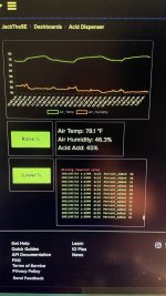
MyAZPool... Thanks very much for the great leads on further enhancements of what I got. A lot to digest and I look forward to doing just that. For the moment, I've completed my Phase 2 objective of having a workable ESP32 timer installed on my IntelliPH, controlled by a dashboard on the internet. Here's a pic of the screen, taken from the AdaFruitIO web dashboard I created for the project:
IMG_0940.jpeg
As you can see I hung an ambient air temp/humidity sensor off the side of the box, and I can raise and lower the acid percent-to-be-added using the green buttons. I made provisions for a future Dallas water temp sensor I have. The fine-print box is a record of the times and amounts of the acid adds (test data, not actual). I measured the output of the pump as one ounce every 10 seconds, and pegged 100% as 24 ounces for each day (Leslie's recommendation for my size pool per four hour window). I divided the acid-add into at most three per day, simulating what the IntelliPH controller did.
When the IntelliPH controller failed, it also disabled the chlorinator, and of course it happened when I was on vacation for three weeks. What a mess.
I looked into that Atlas Probe, but it didn't seem suitable for full time sampling of flowing water. But it would be nice to have a closed-loop control on the ph, so I may investigate further.
 
  • Like
Reactions: MyAZPool
I looked into that Atlas Probe, but it didn't seem suitable for full time sampling of flowing water. But it would be nice to have a closed-loop control on the ph, so I may investigate further.

The Atlas industrial pH probe will absolutely do full time sampling of flowing water. I have it plumbed into system and its bang on for pH monitoring. You can check out my signature for the pH probe project.
 
  • Like
Reactions: MyAZPool
@JackthesE
Wow, pretty cool... Looks as though you have whipped that ipH into submission. :goodjob: I like it.
I like how you recorded the dosing times and amounts.
A few of us are doing something similar but again, dosing is predicated upon pH readings and not time exclusively.
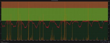
In this Grafana chart, you can see my dosing events (max per event=200mL) based on pH readings and the amounts (right Y axis) and the pH level (left Y axis). Amounts are in mL.
2021-07-19_15-12-15.jpg

This capability is based on njspC and REM (links in my previous post) and using Influx for data collection and Grafana for graphing. I'm merely a user of this setup (I'm not nearly smart enough for the development of it), but I do take a little credit for being a part time guinea pig at times. :p

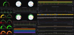
I got to concur with @Katodude (who helped me initially get started down this path), above regarding sampling rates etc. of the Atlas probes. I have three probes plumbed into a sensor bypass manifold (pH/Temp, EC, ORP). I don't know the exact sampling rate but I believe it to be more than once a second for sure. I'm running my filter pump 24x7 (at either 700 rpm or 1200 rpm depending on the time of day) and my sensors are producing data 24x7 as evidenced by my Grafana dashboard.
2021-07-19_15-27-24.jpg

When I tested the flow rate of my peristaltic pump, I got pretty much the same numbers as you but slightly different.
After 3 different flow tests, I came up with 108mL/60 seconds. That's about 1.2 Fl. Oz. (US)/10 seconds.

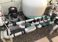
Here is a photo of my "closed loop" sensor bypass manifold if this helps you out at all. Also, there are other members here that have developed different types of solutions regarding sensor manifolds.
2021-07-19_15-34-34.jpg

Again, nice work on the improvements to the IntellipH and thanks for sharing..
r.
 
Last edited:
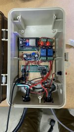
So, here's the final implementation, installed in the original controller box for convenience. A couple of notes....
(1) I added the "red button" on the right side of the box exterior, and pushing it forces a 4 ounce acid add, just in case I need it.
(2) I added logic to suppress acid add if the air temperature is below 40 degrees F. That's rare here in SoCal, but it happens. I didn't want acid adds during freeze protection runs.
(3) I installed a separate flow switch, and use the signal in the logic to make sure there is no acid added unless flow is detected. I'm sure the Pentair controller board did this using the flow sensor built into the IC40, with the alert coming over the RS485 data bus. I didn't want to mess with swallowing the 485 signal and decoding it in the ESP32--this was just an easy way out.
(3) The ESP32 sends a text notification to my iPhone if either of the above two fault conditions are detected.
(4) I save all important data in the ESP32 nonvolatile memory as the program executes throughout the day. That way I can depower/repower the ESP32, and it remembers where it was in the dispensing cycle.

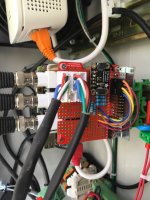
IN the pic below...
(a) the ESP32 is in the upper left (Red LED is power-on, Blue LED means connected to WiFi, the internet and the AdafruitIO website where my dashboard is located.
(b) the two relays are in the upper right, red lights show during acid dispense (IC40 off, acid pump on)
(c) Unit is powered by a 19 vdc wall wart (not shown) from an old router I had. 19 vdc powers the acid pump just fine, and the buck converter (middle left) takes 19vdc down to 5.1 vdc to power the ESP32. Small Green LED in upper right corner means normal operation.
(d) The white gridded thing to the right of the box is a DH22 air temp/humidity sensor connected to the grey cable coming out of the box bottom.
IMG_0950.jpeg

My objective for this project was to replace a failed controller board, and I'm done with that.

But now I've been exposed to some of the very impressive things some of you have done, and I'm inspired to do more! Maybe I'll get that Atlas probe and close the loop. Maybe I rig a "low acid" sensor on the acid tank and send a notification to my phone. Maybe I'll crack that RS 485 and report all its data to my dashboard. Sky's the limit!
 

Enjoying this content?

Support TFP with a donation.

Give Support
So, software is never done, you know? Neither are projects like this, because you always dream up improvements. So a couple of things...

(1) I generalized the time-tagged data log displayed on my dashboard to do more than just report the percent of the acid adds. It now reports additional kinds of events like (a) controller turned ON, (b) flow switch ON/OFF events, (c) total acid-added for the day, (d) text messages sent, etc., etc., etc. The acid-added for the day is the total amount including automatic and manual adds, and displays ounces-added and a recommended auto-add percent as an advisory. Also comes to me as a text message at 4:00 pm, which is a nice cocktail hour reminder too.

(2) I wanted to know how much acid was in the holding tank, and I thought the best way to do that was to weigh the tank, and calculate the acid level in gallons from that. I ordered a "digital bathroom scale kit" having 4 load cells and associated electronics from Amazon ($8). It puts out a signal that can be read by the ESP32. I'll display the gallons-left on the dashboard, and send a text alert if acid gets low. One complication is that periodically the scale has to be calibrated with no weight on the scale, so I'll have to figure out a mechanism that will lift off the tank a bit while it calibrates. Anyone out there figure out an easier way to measure acid level?

Really impressive work there. :goodjob:
MyAZPool... hey thanks. I've now gone through some of the reference materials you cited describing your system and WOW!--We are not worthy. A lot of thought and a very professional result are both apparent. One tip I picked up was the snubber you used to protect the power supply. I ordered the same snubber from Amazon ($7.40), to protect the relay contacts that controls the IC40. Contacts are rated at 30 VDC, but is switching up to 40 VDC at IC turn-on. Thanks for the tip.
 
  • Like
Reactions: MyAZPool
@JackthesE
Hey nice, and thanks but a lot of credit goes to many others who I got advice from, who developed the software that I am using, etc. That also applies to my using the snubber circuit that I am incorporating. That particular idea came from @rstrouse and who has a very similar system and who is also the developer of njspC-dashPanel, REM, Nixie and who has been kind enough to contribute immensely to many of our "homebrew" automation endeavors.

I just took all the advice that I could find and set to work on the hardware. Many things I did exactly as advised and other things I kind of deviated here and there to suit my own needs and desires. All the software development credit goes to @rstrouse and @tagyoureit . Without the software components, I'd have nothing more than some sensors and a bunch of useless wiring, components and circuit boards. :p

Maybe take a look at the way that nodejs-poolController/REM Chem calculates remaining liquid in the tank.
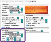
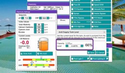
You tell the software what the usable tank capacity is and what the flow rate of the pump is (mL/min). From there, every time the system doses, it subtracts that exact amount from the remaining amount. When you fill the tank back up, you simply tell the software of that fact and it makes the necessary adjustments from there.

2021-07-30_13-59-05.jpg 2021-07-30_14-01-19.jpg
 
Last edited:
Maybe take a look at the way that nodejs-poolController/REM Chem calculates remaining liquid in the tank.
MyAZPool...I kept noodling for a way to directly measure the remaining acid level with some kind of a sensor. I evaluated four ideas, and here is the winner:
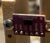
I bought a tiny device (a VL53LO chip mounted on a development board, two for $13 on Amazon). The device can very accurately measure the liquid level height directly, to about 2mm accuracy. That tiny chip on the board in the pic emits an invisible laser beam that reflects off the liquid surface back to a photo sensor. Transit time of the beam is converted into distance. The chip communicates that distance back to my ESP32 using a standard i2C interface. The laser beam is very narrow, and I had no problem pointing it past the grid to see the acid surface in the tank. That's a 3mm screw head holding the board to a jig in the pic, so the device is really, really tiny.
Picture1.png
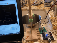
The second pic shows the experimental rig I used for a test to measure the surface level of a pot I was filling with water in a kitchen sink.
Picture3.png
It's a little hard to see the sensor above the pot looking down, but you can see the graph of measured distance to the water surface on the laptop, as I filled the pot.

So what remains for me is to productize the sensor so it can function and survive in the awful vapors above the acid. It will be hermetically sealed inside a plastic enclosure of some sort with an acrylic window for the optics. I'll keep you informed of my progress...Jack
 
  • Wow
Reactions: MyAZPool
@JackthesE
Wow, this is very interesting. I for one are very anxious to follow your continuing experiments and your ultimate findings/solutions on this front.
Yes, please keep us informed of your progress. :thumleft:
Thanks very much.
r.
 
anxious to follow your continuing experiments and your ultimate findings/solutions
So I did a little packaging and installed the sensor in my tank, and it works very, very well, with a few caveats I'll cover below.
First some pics:
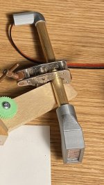
IMG_0974.jpegIMG_0975.jpegIMG_0977.jpeg
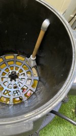
I designed and 3d printed a sensor housing for the sensor board, Pic 1. It has an acrylic window, but more on that later. The housing interfaces with a 3/8" brass tube for the sensor wires, and routes to an elbow, also 3d printed. I installed the assembly in the tank as shown in Pic 3. My goal was to still be able to invert a gallon jug of acid and put it on the grid spike for ease of filling. No problem doing that.

For my initial trials I measured the distance from the acid surface at my particular fill level to the top of the grid and I got 154mm (+-about 3mm I would guess). The raw sensor output was 165 mm, so I introduced a bias of 11 mm so the compensated sensor reading was 154 mm too. At least part of that bias is understandable, since the detector chip is above the tank grid top. Then the big test: I forced a 4 ounce acid dispense into my pool, and I had calculated that the surface would lower by 1.9 mm. The sensor saw that change, although there was some toggling between 1 and 2 mm. I declared victory.

Now, for the caveats...
(1) The acrylic window introduced a surprising loss of sensitivity, so I drilled a small slot just big enough for the chip to look through. I don't know how the optics ae going to hold up now that they are exposed to the saturated acid vapor in the tank. Time will tell, and I may try some real glass to restore hermeticity as an alternative if needed.
(2) When I was struggling with Caveat #1, I thought that the problem might be related to detecting the surface of a relatively clear liquid in dark conditions. So I introduced some white floating targets to see if that would help. It didn't, but if you look closely at pic 3 above, you can see some white floating targets in the acid. There are seven of them, 60 mm in diameter. Given I have addressed Caveat #1, I don't know if the targets are really needed, but I don't plan on fishing them out either.
(3) This is more of a design issue rather than a caveat: I had everything working well with the sensor leads 14" long, but when I made up a 6' cable to reach over to my ESP32, the sensor would not initiate reliably. I2C is not really meant to be robust at these kind of line lengths. My simple solution was to place an Arduino Nano (still $3 on Amazon) at the acid tank, and use a serial bus to transmit the data over to the ESP32.

Next steps:
(1) I'll design an enclosure for the Nano and install it on the side of the acid tank
(2) I need cabling for power over to the Nano from the ESP, and then serial data back.
(3) I'll have to figure out the arithmetic for translating the mm measurements to gallons left in the tank.
(4) And finally, all my testing has been done with a nearly full acid tank, but the ultimate utility is when the acid gets low. Hope it continues to work well.

 
Hey Jack, I am following this as well. Some comments…

I have found the muriatic acid (I use 32% in my tank) to be extremely corrosive around my buried acid tank. It has destroyed my buried tank hinges, a stainless steel temperature probe, and four “chemically hardened” Milone eTapes (at which point I gave up on, haha). I am anxious to see if the electronics deteriorate with the opening you have drilled for the optics. The other issue you might have with the window is keeping it clean (even with glass) due to condensation (acid fumes, moisture, stuff in the air).

Like you, I have considered some other options for measuring my acid tank level, but haven’t pulled the trigger. The Milone eTape has been flawless for measuring the level of my chlorine tank, and I would love that same level of accuracy for my acid tank. I am hoping your project works…thanks and keep us updated!
 
@JackthesE
Definitely some good stuff there. I'm also interested to see how the electronics hold up in that environment. I'm hoping by using the glass to seal things back up, hopefully that will be the ticket.
As far as extending your I2C signal, you might have a look at the AdaFruit LTC4311.

I'm using one on my I2C bus now and I do think it helps with my I2C signals. Prior to installing it on my RPi stack via an "I/O / I2C Extender Board", I was having some issues that I believe were due to I2C signal loss and now everything is performing great.
9F85EA7A-12E4-4B26-8CA6-219A2E4AECAF_1_105_c.jpeg A16C3FE6-D0B2-493F-942D-6383424F3E66_1_105_c.jpeg

This board was an idea that @rstrouse came up with and who suggested that I try this. Many thanks to him for holding my hand through the process of gathering up the necessary parts and assisting me step-by-step, in putting this board together. I did not have the necessary knowledge or skill sets in order to accomplish this task, without his excellent help. 🙏
r.
 
  • Like
Reactions: jonpcar
That I2c active terminator is pretty clever and does a great job. I would be curious to see how well the brass and aluminum parts survive the gasses from the tank. I found out recently, that 318 stainless will begin to corrode if exposed to the gas. The alloys start to leach out.

Thermoplastics including PVC are your friend here. If you have exposure to the board, perhaps a product like Corrosion-X might slow down damage.
 
I have found the muriatic acid (I use 32% in my tank) to be extremely corrosive
And it turns out the acid vapors were, indeed, fatal to my exposed sensor setup: after only one day inside the tank, every metallic surface including solder joints had a green or gray patina, and the sensor had failed electrically. So I knew I had to have a hermetic enclosure for the sensor, and I needed to find a transparent window material as part of the solution.

So I had another sensor, and my next step was to see if any transparent material I had on hand would allow the sensor to work correctly. Short answer is no. So far I've looked at 3mm acrylic, 3mm glass, 0.4mm plastic of some sort, and Costco shrink wrap. The two thicker materials both failed miserably. The 0.4mm plastic looked a little better, but had severe non-linear behavior under 100mm distance and beyond that distance it did not function. The shrink wrap allowed the sensor to work just fine, but it's hardly durable enough to be used for the purpose. So my conclusion so far is that using the VL53LO optical sensor is simply not going to work.

For completeness, I thought I'd mention a couple of other options that I considered earlier and discarded:
(1) I thought about measuring the weight of the entire tank, acid and all, using a set of load cells and an HX711 electronics chip, commonly used in bathroom scales. I had such a sensor set from a previous hobby project. I discarded this path because my acid tank is bolted to a slab of concrete (this is earthquake country, after all!).
(2) I made an "acid displacement probe" out of an 18" piece of sprinkler pipe, empty and sealed at both ends. I attached a vertical load cell to measure the net of the probe weight and the buoyancy force (equal to the weight of the displaced acid at any given immersion level). This rig worked OK in my pool water, but, again, the load cell is made out of aluminum and its sensing elements are electrical strain gauges, so putting that inside the tank would fail for the same reasons that the VL53LO did.
(3) I thought about putting a magnet on a float, constrained within a sprinkler pipe mounted inside the tank. The magnet's vertical position could be detected by one or more reed switches on the outside of the tank. While I think this could be made to work, it would only provide a coarse resolution of the acid level at best. Perhaps that's good enough to trigger a text message to refill the holding tank.

So I'm up for any other ideas you all might have. I've enjoyed this project along the way, and I really enjoyed the interaction with a knowledgeable group of folks. Thanks for that...Jack
 
Honestly, that pump is rated at right around 120mL/min. If you take a beaker out there and run the pump for a minute into that beaker from the check valve at the injection point it will give you an incredibly accurate flow rate. Mine is 112.5 mL/min. One of the primary uses of a peristaltic pump is to dispense very accurate volumes. Because of its design, volume is a function of the cam speed which is very easy to regulate. If you use this flow and the starting level of the tank you will always know the level of the liquid. When you take a gallon and invert it into the tank add a gallon to the current volume. It's really simple and stupid accurate.
 

Enjoying this content?

Support TFP with a donation.

Give Support
Thread Status
Hello , This thread has been inactive for over 60 days. New postings here are unlikely to be seen or responded to by other members. For better visibility, consider Starting A New Thread.