Hayward AquaLogic
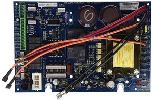
The Hayward Goldline AquaLogic automation and chlorination models AQL-PS-4, AQL-PS-8-V, AQL-PS-8 AQL-PS-16-V, AQL-PS-16 use the GLX-PCB-MAIN board.
Goldline introduced AquaLogic in 2003. Hayward acquired Goldline in August of 2004. Hayward discontinued AquaLogic in 2008 and replaced it with Hayward ProLogic.
ProLogic/Aqualogic Troubleshooting Guide is a good place to start with problems.
Low Salt
Low salt messages are often the first indication of a failing cell. Don't add salt until you verify the water salt level with a Taylor K-1766 Test Kit or Salt test strips.
High Salt/Amps
The high salt warning comes on when the current exceeds 8 amps. This can be caused by high salt but also by high water temperatures. [1]
Check under the diagnostics menu for the correct cell size. If you select the cell size to t-3, t-5 or t-9 instead of the correct t-15 then the salt readout from the controller will be high salt.[2]
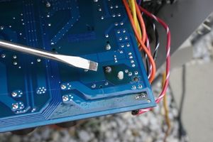
Common cause is failure of the solder joint to the K1 relay.[3] The K1 relay does not need to be replaced. It only needs to be re-soldered. To check if this might be your problem, unscrew the mother board and turn it over, if there is black smoke/burn marks at the K1 relay solder point, this is likely your problem.
Temperature Sensor
The temperature sensor is a standard 10K ohm thermistor.
Replacement part number is GLX-PC-12-KIT. A clamp holds on the sensor and the two wires go into a terminal block in the box. Make sure that all power if off before going in the box and don't do anything that you are not sure you can do safely.[4]
Aqualogic Losing Time
The clock does not keep proper time.[5]
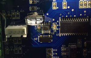
You can replace the board or try repairing the board. On the board it has a capacitor on the left top corner, it's like a double battery in wrap. You can buy on Ebay for about $3 and 5 mins to replace it. After replacement you run for 1 hr it will charge the battery.[6]
On the board:
- U1-Microprocessor is PIC18F2620 (28 pin version)
- U2-Real Time Clock is Dallas / Maxim RTC is $3.50 at Digikey (DS1302Z+CT-ND)
- C3-Super Cap is 5v and .33UF Digi-Key KR-5R5V334-R
- X2-is a 32.768 kHz Crystal Epson MC-306 / 6 pF (SER4099CT-ND at Digikey) and costs $.046
Some people replaced just the C3 capacitor, others repalced C3 and X2, and others replaced U2, X2 and C3.[7] Replacing U2 and X2 is not an easy soldering job if you are not used to surface mount parts, don't try it.
After replacing parts you need to wait about 24 hours for the real time clock to start working and then adjusting it to current time.
Tips
- high amps can "blow" the solder joint and that high amps are most often caused by salt levels being too high.
- You should not add salt directly to the skimmer boxes as it will cause an extremely high salinity level as the salt was being dissolved and pulled through the system.
- It is recommended to turn off the turbocell before adding salt
- the motherboard has a 20 amp fuse on it. Unfortunately it seems the Amp limit on the relay is 20 amps too. It has been strongly recommended to replace the 20 amp fuse with a 15 Amp fuse to thus protect the relay and the K1 solder point.
- The K1 and K2 carry the DC low voltage (polarity reversal) to the salt cell.[8]
- The K1 problem causes amps to always be exactly zero.[9]
- Use a 30 watt soldering iron and 60/40% rosin core (solder lead)
- Your don’t have to unhook mother board wires. Just turn it over. Make sure it is level before adding solder.[10]
- There are different versions of the main board. You can find various pictures in this thread.
.
- ↑ https://www.troublefreepool.com/threads/aqua-logic-salt-too-high-cholrinator-off-high-salt-amps.34466/post-1256487
- ↑ https://www.troublefreepool.com/threads/aqua-logic-salt-too-high-cholrinator-off-high-salt-amps.34466/post-287663
- ↑ https://www.troublefreepool.com/threads/aqua-logic-salt-too-high-cholrinator-off-high-salt-amps.34466/post-310225
- ↑ https://www.troublefreepool.com/threads/water-sensor-open-default-code.79551/post-682536
- ↑ https://www.troublefreepool.com/threads/aqualogic-losing-time.57949/
- ↑ https://www.troublefreepool.com/threads/aqualogic-losing-time.57949/post-1494728
- ↑ https://www.troublefreepool.com/threads/aqualogic-losing-time.57949/post-1547883
- ↑ https://www.troublefreepool.com/threads/lightning-took-out-power-to-aquatrol-display.168439/post-1485894
- ↑ https://www.troublefreepool.com/threads/aqua-logic-salt-too-high-cholrinator-off-high-salt-amps.34466/post-657023
- ↑ https://www.troublefreepool.com/threads/aqua-logic-salt-too-high-cholrinator-off-high-salt-amps.34466/post-1638689


