I think the 3 way at the bubblers will not be needed. I mean, once the proper settings are met - should be set and forget? Unless, by others features being opened - will the flow of all features change. (Or can/should I correct that by ramping up the pump gpm to compensate).
So, I assume you propose to put 2-ways on the bubblers as well? You can do that. I'm just not a fan of multiple 2-ways wherever it can be avoided (i.e. the bubblers), but in the case of the Laminars and FW bowls, I don't think there are any other options. Your call on bubbler valves. Just let me know and I will help amend the diagram.
I mean it is a variable flow pump, so i assume I should be able to calculate the exact gpm needed to run what ever combo of features i have running?
With your particular pump, you can have up to eight (8) different pump speed or flow settings (based on different requirements). You can assign those pump settings to Feature Circuits and those Feature Circuits will be used (embedded) within the CIRCUIT Groups. Here is an example:
1. Pump Flow - 30GPM - NAME: (PUMP 30)
2. Pump Flow - 50GPM - NAME: (PUMP 50)
3. Pump Flow - 80GPM - NAME: (PUMP 80)
4. Pump Flow - 110GPM - NAME: (PUMP 110)
5. Pump Speed - 1000RPM - NAME: (SPEED 1000)
6. Pump Speed - 1300RPM - NAME: (SPEED 1300)
7. Pump Speed - 1800RPM - NAME: (SPEED 1800)
8. Pump Speed - 2200RPM - NAME: (SPEED 2200)
NOTE: With your particular pump, you can use either Pump Flow (GPM) or Speed (RPM). You can have all eight (8) setup for flow or all eight (8) setup for speed or any combination of the two. For your Features Pump, I might just use speeds. You'll have to experiment and see which speeds (or flow) work best for whatever water features you want going at the same time.
Now, you create Feature Circuits for all eight (8) speeds or flow settings that you have setup in your "Pumps page". To avoid confusion, name the feature circuits the same as what you named the Pump settings.
Now you create Circuit Groups (macros) that contain those Feature Circuits.
Here is an example:
Circuit Group: BUBBLAM (This has only the bubblers and laminars operating)
Feature Circuit: LAMINAR ONLY (this would close the valve diverter to the firewater bowls)
AUX Circuit: WF PUMP (this turns on your water features pump)
NOTE: The feature circuit that controls the IntelliValve that diverts water to either the bubblers or the other two types of features (to the right of the pump) does not need to be activated since it is already in its HOME position.
I know it's a bit complex but then again you have a "complex" setup. I can guess that it might be confusing right now, but you'll see exactly how it all works, once you get it all setup and going.
The possibilities are kind of endless with your configurations and only restricted to the limitations of the automation. And there are some to be sure, which I will try to address in your next comment.
The heaters........Here is my thinking. If we set commands up to go something like this:
Have gas heater bring pool temp to 82 degrees and stop.
If temp is greater than 81 degrees, have heat/pump maintain a 83 degree temp
If temp is greater than 84 degrees, have chiller bring temp back to 83.
Or something along those lines, so maybe it is better to plumb separate? Just brainstorming.
John, are you suggesting that once the water temperature gets to 82, that the automation will turn the mastertemp off and bring the ultratemp online? I don't think the automation will do anything like that. I scoured the documentation for a feature or setup like you are describing and I am lost on trying to find anything like that. Did you get this idea from the heater documentation(s)?
Someone else may have a better idea, but I think the only way you can do what you are trying to do (use the MasterTemp to rapidly heat the water and then use the UltraTemp to maintain the temperature) is like this.
1. Manually activate the MasterTemp through the automation (Turn on). Allow the MasterTemp to bring the temp to 82 degrees.
2. Then, manually de-activate the MasterTemp through the automation, once the water temp is 82 degrees (turn off).
3. Then activate the UltraTemp and allow the automation to maintain the temperature of the water.
Here is my own personal understanding of how the automation addresses the activation or deactivation of heaters. It goes something like this.
A particular heater is either turned on or turned off. Period. You can have more than one heater but I'm pretty sure that they do not act "in concert" with one another as I think you might be describing. When a heater is on and it reaches its "set point" temperature, it cuts off, when the water cools down a degree or two, it turns back on. The automation determines the temperature of the water from the readings it gets from the Water Temperature Sensor. That's my version. I think @Jimrahbe, describes how this works maybe better than I do.
I believe that the only thing that will "cool" the water back down, is the fact that the heater is 1. no longer on, 2. time, and 3. ambient air temperature. The combination of those three determines the "cool down" of the water I believe (simplified).
SEE POST #298 FOR UPDATED INFORMATION REGARDING THIS TOPIC.
Speaking of relays, here is just a draft of how you might consider configuring them (I also included a draft of the circuit breaker configs.). In this version, you have two spare relays and one spare 1 pole breaker slot. This outline is based on the fact that you indicated that you DID want to take advantage of a separate relay for the IntelliChlor. Note: This is not a "Final" just a draft, so please don't beat me up too bad

.
***DIAGRAM DELETED*** - DUE TO REVISIONS, PLEASE SEE LATER POSTS WITHIN THIS THREAD FOR NEWER REVISIONS OF THIS DIAGRAM.
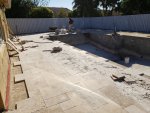
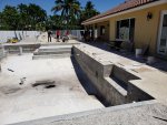
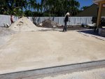
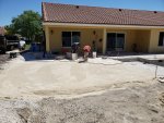
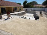
Okay, have fun forming the equipment pad. I got my own chores awaiting me today.
r.
 . I got an alligator or two here at the homestead that I got to shake off and then I'll be all over it.


