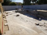
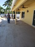
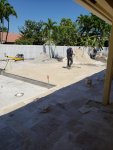
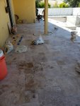
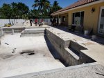
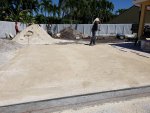
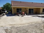
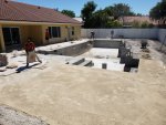
South Florida - New In-ground Large Build

John_and_Val
Give me some time with your comments and questions, and I'll have something for you within a day or two (Rev3) ;). I got an alligator or two here at the homestead that I got to shake off and then I'll be all over it.
r.
 
I have a question in regards to the SWG....is there any problem with having the "Chlorinated" Water coming out of the spa jets with direct skin contact? Not sure if the amount is significant. If it might be a problem, should we plumb that on the pool return line only?

On the Intellicenter you will set it so when in SPA mode it will reduce the SWG % output to a very low level.
 
On the Intellicenter you will set it so when in SPA mode it will reduce the SWG % output to a very low level.

Copy that.....

@bdavis466 @kimkats
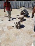
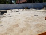
On the table........while out watching the travertine go in I studied it real hard. Here is what i came up with.....I think making it permanent is best. Too many Issues with a adjustable table top.
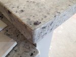
What do you think of some cool looking piece of granite? I can get a piece, have them cut it....say 3' x 4'. Have them cut 2 pieces and epoxy them together (for strength). Then have them do a 3" or 4" border around it (just like they do in kitchens). I can have them drill "cup holders" into it......and an umbrella sleeve. The cup holders will get polished so everything will be nice and shinny!!!! Then I can epoxy that bad boy to the pedestal and should never have an issue.
Let me know.
@MyAZPool .............. take your time....

Just a quick search brought this up.....Travertine-countertop-2-1024x576.jpg
 
Last edited:
Decking first!!!! LOVE IT!!!! They got a LOT done!! SWEET!

Skimmer cover-IF they are true artists with with a big saw they can use a piece of that travs. and cut finger holes in it instead of using the "common" covers.

Get some blue tape to mark any pieces you don't like-chipped corner, "ugly", whatever.

Now the table-Now that is an idea. Two pieces should be thick/strong enough to hold up to most anything. Will the two pieces make it high enough to solve the water over it problem? When you say border where do you mean it will go?

Kim:kim:
 
  • Like
Reactions: MyAZPool
Hey John_and_Val,
Before I get Rev3 out to you, I'll try to answer your questions and then I got two for you.
@bdavis466 @MyAZPool
I don't mind the 3 way at the bubblers, but I am still a little confused on how to "throttle" them with the 3 way? The 3 way at the pump will give me water to the bubblers, but the 3 way at the bubblers will only be able to move water from one bubbler to the other, right? Or am i missing something?
Yes, Correct! The 3-way between the bubblers will equalize the bubblers. The 3-way just to the right of the Features Pump controls how much flow goes to the bubblers. So first you would equalize the bubblers by adjusting the 3-way between them. Then you would control the amount of water to the bubblers with the 3-way to the right of the features pump.
In other words, the 3-way to the right of the features pump, is used to "throttle back" the amount of flow to the bubblers and the 3-way between the bubblers, equalizes them.

Looking at this closer, I really don't think that you need an IntelliValve on that valve between the bubblers. IOW, manual adjustment only (just like the 2-ways) or in your words (set and forget). Do you agree? If so, let me know and I will make the change.

Note: In Rev3, I will number the valves, so it will be easier to refer to them.

@bdavis466 @MyAZPool
I have a question in regards to the SWG....is there any problem with having the "Chlorinated" Water coming out of the spa jets with direct skin contact? Not sure if the amount is significant. If it might be a problem, should we plumb that on the pool return line only?

So, there are a couple of ways to address this in my opinion.
1. You can have a separate circuit for the SWCG. That is the way that I wired mine and it gives me maximum control over when I want the IC-60 (and the IntellipH) to be energized or not. I really like the way that I did it (I didn't think of it, I got the idea from some other members here) and if I were to wire all over again, I would do exactly the same thing. Then, the IC-60 is only on when I want it on through control of the relay. Dont, worry, it (IC-60 and my IpH) cannot be energized if the pump is not energized because the Line side of the IC-60/ipH relay is wired through the Load side of the pump relay. Control is determined all through the Circuit Groups. If you still have questions regarding this method, I can provide further information. Here is the thing. Initially, it might seem a bit confusing but I believe that once you get your arms around the whole concept of programming with AUX circuits, Features Circuits and Circuit Groups (macros), you'll like it I think.

2. Like you suggested, we can plumb the IC-60 to the Pool Return Jets. Sure! That is super simple.
3. Or you can do both 1. and 2.

Okay, for my questions...
Question 1. On the heaters. Are you just thinking on plumbing straight through from one heater through the other? No valves right? I can't think of any reason why this wouldn't be your best bet.
Question 2. I assume the Master Temp is plumbed first, then the Ultratemp 2nd?

Get back with me and I will get crackin on Rev3.

In addition, I have also been doing some preliminary work on your..
a) Main Load Center and Expansion Load Center Circuit Breaker setups (with wiring diagrams).
b) AUX Circuits (relays) w/wiring.
c) Transformer wiring (from the lights, to a master transformer enclosure, then to the two load centers.
More to follow on those if you are interested.
r.
 
@kimkats
If the large piece is cut at 3' x 4' with a mitered 45 degree on the ends.........we cut 2 of them
Then they cut a "border" any thickness i want. and that is what gets glued to the outside edges of the big piece. By doing this we can give the appearance of any thickness we want. I attached a quick example.

@MyAZPool
I think the 3 way at the bubblers will not be needed. I mean, once the proper settings are met - should be set and forget? Unless, by others features being opened - will the flow of all features change. (Or can/should I correct that by ramping up the pump gpm to compensate). I mean it is a variable flow pump, so i assume I should be able to calculate the exact gpm needed to run what ever combo of features i have running?
SWG - 1 and 2 *(If i go with the expansion board, we should have plenty of circuits, relays....what ever they are called! JK)
The heaters........Here is my thinking. If we set commands up to go something like this:
Have gas heater bring pool temp to 82 degrees and stop.
If temp is greater than 81 degrees, have heat/pump maintain a 83 degree temp
If temp is greater than 84 degrees, have chiller bring temp back to 83.

Or something along those lines, so maybe it is better to plumb separate? Just brainstorming.

let me know and can't wait to see the wiring!!!!!

Going to get outside and start forming up the part 1 of the equipment pad while the travertine guys are doing there thing. Val was in shock with how much they got done!
They should easily have it all done today - including a lot of cuts.
 

Attachments

  • mitered granite example.jpg
    mitered granite example.jpg
    30.9 KB · Views: 17
Man that looks pretty. You have to look VERY close to even see where the pieces meet. I am guessing you have someone picked out to do the work? They need to be the A-Team for such good work as the example!

Have you thought about doing a "statement piece" for the table top? Something EXTRA special.....totally different than the decking and such. Make it really stand out. Just thinking out loud but not sure if it is a good idea. See what Val thinks. I have seen some stone that is darker with a really neat light vain running through it.

Kim:kim:
 
SIGH...................oh yea! That IS what I mean!!! YOU? YOU built that??? You have MAD SKILLS! I love the piece going up the wall. What even gave you that wonderful idea? It is like a work of art up there! How did you get it to stay there? I can't wait to see it lit up!!! LOL on not lighting up the pool table.................why not??? hehe

Kim:kim:
 

Enjoying this content?

Support TFP with a donation.

Give Support
I think the 3 way at the bubblers will not be needed. I mean, once the proper settings are met - should be set and forget? Unless, by others features being opened - will the flow of all features change. (Or can/should I correct that by ramping up the pump gpm to compensate).
So, I assume you propose to put 2-ways on the bubblers as well? You can do that. I'm just not a fan of multiple 2-ways wherever it can be avoided (i.e. the bubblers), but in the case of the Laminars and FW bowls, I don't think there are any other options. Your call on bubbler valves. Just let me know and I will help amend the diagram.

I mean it is a variable flow pump, so i assume I should be able to calculate the exact gpm needed to run what ever combo of features i have running?
With your particular pump, you can have up to eight (8) different pump speed or flow settings (based on different requirements). You can assign those pump settings to Feature Circuits and those Feature Circuits will be used (embedded) within the CIRCUIT Groups. Here is an example:
1. Pump Flow - 30GPM - NAME: (PUMP 30)​
2. Pump Flow - 50GPM - NAME: (PUMP 50)​
3. Pump Flow - 80GPM - NAME: (PUMP 80)​
4. Pump Flow - 110GPM - NAME: (PUMP 110)​
5. Pump Speed - 1000RPM - NAME: (SPEED 1000)​
6. Pump Speed - 1300RPM - NAME: (SPEED 1300)​
7. Pump Speed - 1800RPM - NAME: (SPEED 1800)​
8. Pump Speed - 2200RPM - NAME: (SPEED 2200)​
NOTE: With your particular pump, you can use either Pump Flow (GPM) or Speed (RPM). You can have all eight (8) setup for flow or all eight (8) setup for speed or any combination of the two. For your Features Pump, I might just use speeds. You'll have to experiment and see which speeds (or flow) work best for whatever water features you want going at the same time.

Now, you create Feature Circuits for all eight (8) speeds or flow settings that you have setup in your "Pumps page". To avoid confusion, name the feature circuits the same as what you named the Pump settings.
Now you create Circuit Groups (macros) that contain those Feature Circuits.
Here is an example:

Circuit Group: BUBBLAM (This has only the bubblers and laminars operating)
Feature Circuit: LAMINAR ONLY (this would close the valve diverter to the firewater bowls)
AUX Circuit: WF PUMP (this turns on your water features pump)
NOTE: The feature circuit that controls the IntelliValve that diverts water to either the bubblers or the other two types of features (to the right of the pump) does not need to be activated since it is already in its HOME position.

I know it's a bit complex but then again you have a "complex" setup. I can guess that it might be confusing right now, but you'll see exactly how it all works, once you get it all setup and going.

The possibilities are kind of endless with your configurations and only restricted to the limitations of the automation. And there are some to be sure, which I will try to address in your next comment.

The heaters........Here is my thinking. If we set commands up to go something like this:
Have gas heater bring pool temp to 82 degrees and stop.
If temp is greater than 81 degrees, have heat/pump maintain a 83 degree temp
If temp is greater than 84 degrees, have chiller bring temp back to 83.
Or something along those lines, so maybe it is better to plumb separate? Just brainstorming.
John, are you suggesting that once the water temperature gets to 82, that the automation will turn the mastertemp off and bring the ultratemp online? I don't think the automation will do anything like that. I scoured the documentation for a feature or setup like you are describing and I am lost on trying to find anything like that. Did you get this idea from the heater documentation(s)?

Someone else may have a better idea, but I think the only way you can do what you are trying to do (use the MasterTemp to rapidly heat the water and then use the UltraTemp to maintain the temperature) is like this.
1. Manually activate the MasterTemp through the automation (Turn on). Allow the MasterTemp to bring the temp to 82 degrees.
2. Then, manually de-activate the MasterTemp through the automation, once the water temp is 82 degrees (turn off).
3. Then activate the UltraTemp and allow the automation to maintain the temperature of the water.

Here is my own personal understanding of how the automation addresses the activation or deactivation of heaters. It goes something like this.
A particular heater is either turned on or turned off. Period. You can have more than one heater but I'm pretty sure that they do not act "in concert" with one another as I think you might be describing. When a heater is on and it reaches its "set point" temperature, it cuts off, when the water cools down a degree or two, it turns back on. The automation determines the temperature of the water from the readings it gets from the Water Temperature Sensor. That's my version. I think @Jimrahbe, describes how this works maybe better than I do.

I believe that the only thing that will "cool" the water back down, is the fact that the heater is 1. no longer on, 2. time, and 3. ambient air temperature. The combination of those three determines the "cool down" of the water I believe (simplified)
. SEE POST #298 FOR UPDATED INFORMATION REGARDING THIS TOPIC.

Speaking of relays, here is just a draft of how you might consider configuring them (I also included a draft of the circuit breaker configs.). In this version, you have two spare relays and one spare 1 pole breaker slot. This outline is based on the fact that you indicated that you DID want to take advantage of a separate relay for the IntelliChlor. Note: This is not a "Final" just a draft, so please don't beat me up too bad :).

***DIAGRAM DELETED*** - DUE TO REVISIONS, PLEASE SEE LATER POSTS WITHIN THIS THREAD FOR NEWER REVISIONS OF THIS DIAGRAM.

Okay, have fun forming the equipment pad. I got my own chores awaiting me today.
r.
 
Last edited:
Wow.....impressive
I have to ask - what background do you have - because it sure looks like some to of engineer?

And Question? How do we power up both panels? I was originaly going to drop a 80 amp breaker in my panel in the garage, send (2) #4 hots and a #8 neutral and a #8 ground as feeders to intellicenter via a 1 1/4" conduit.

do the #7 and #8 breaker spots power up the #1 and #2 slots on the second panel?

and what is SPD? (#8 and 9 on first panel)?
 
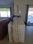
@kimkats @bdavis466 20171215_172139.jpg20171221_193417.jpg20171221_193624.jpg20171222_125500.jpg20171224_171228.jpg
For your viewing pleasure:
First one is my test piece........then a paneled it with a special acrylic that allows light to pass through it. So you edge light it and the panel glows.....then place a translucent stone over top - such as this onyx and BAM!!!!! you have a back lit bar! Stew on that for a while! Ice maker is to the left of wine cooler, and the rest are drawers for glasses, liquor etc....... but i have one more thing that is the coolest (literally) thing about the bar!!!!
 
John_and_Val
Wow.....impressive
I have to ask - what background do you have - because it sure looks like some to of engineer?
Nope, Just an aviation background. Nothing fancy at all :)...

And Question? How do we power up both panels? I was originaly going to drop a 80 amp breaker in my panel in the garage, send (2) #4 hots and a #8 neutral and a #8 ground as feeders to intellicenter via a 1 1/4" conduit. do the #7 and #8 breaker spots power up (the expansion panel).
YES. Run your power feeds from the panel in the garage to the IntelliCenter Main Load Center L1, L2, Neutral bus bar and ground bus bar.. Then feed the Expansion Load Center through the 30 amp breaker (slots 7/8). Your specs look good except that I might personally do a #4 neutral and a #6 ground but just check with a reliable licensed electrician and if he says your specs meet code for your local area, then you're good-to-go).

power up the #1 and #2 slots on the second panel?
NO.
1. Run #10 L1 and L2 feeds from the 30 amp breaker in the Main Load Center to the L1 and L2 lugs in the Expansion Load Center.
2. Run a neutral feed #10, from the neutral bus bar in the Main Load Center to the neutral bus bar in the Expansion Load Center.
3. Run a ground feed #10, from the ground bus bar in the Main Load Center to the ground bus bar in the Expansion Load Center.
The 30 amp breaker in the Main Load Center now controls the power to the Expansion Load Center.

NOTE: That is ONLY how I would do it and I would ALWAYS consult with my commercial electrician buddy just to get a "reality check" before proceeding. I highly recommend that you just run this by a licensed electrician FIRST, to ensure it meets the code requirements in YOUR local area!

and what is SPD? (#8 and 9 on first panel)?
Surge Protection Device. In a previous post in your thread, I highly recommended it. I personally really like the Siemens model ( I have one on my house "Main Panel/Service Entrance, one on my shed sub-panel and one on my IntelliCenter Load Center, but others here may prefer other various brands. Compare the specs and recommendations and make your own decisions.
NOTE: You can see it attached to the bottom of my Load Center (Siemens First Surge) in Post #204 of this thread.
r.
 
Last edited:
John_and_Val
I got bored this evening, so I decided to do a bit more work on your project.
Here is REV2 of the Load Center diagram. I just added more connections essentially. I did not connect everything because it would be "too busy". But at least you can get the idea.

***DIAGRAM DELETED*** - DUE TO REVISIONS, PLEASE SEE LATER POSTS WITHIN THIS THREAD FOR NEWER REVISIONS OF THIS DIAGRAM.

Here is how I might envision a NEMA 4 enclosure large enough to house your 14 low voltage transformers (if you don't want as many boxes hanging on your wall) AND as many conduits trying to connect to your two (2) Load Centers (that would be a mess).
2019-03-23_23-07-54.jpg
Let me know if you have any questions. Your electrician should have a pretty good idea of what I am getting at here.
NOTE: Of course, this enclosure should have the proper "Bonding" just like any other enclosure/Load Center. I guess it's pretty much assumed that each and every Pentair Lighting Transformer will need to be removed from its existing enclosure. Goes without saying :)....

All the best.
r.
 
Last edited:

Enjoying this content?

Support TFP with a donation.

Give Support
Thread Status
Hello , This thread has been inactive for over 60 days. New postings here are unlikely to be seen or responded to by other members. For better visibility, consider Starting A New Thread.