@mas985 Only thing though is that by what I understand the MDs are also useful as a backup for the skimmer if water level goes bellow skimmer they get into play saving my pump's life... So... Uffff I hate mistakes!That would work!
Mid-Construction DIY - STUCK! - PLEASE HELP!!!
- Thread starter shlomikalfa
- Start date
You are using an out of date browser. It may not display this or other websites correctly.
You should upgrade or use an alternative browser.
You should upgrade or use an alternative browser.
- May 3, 2007
- 18,073
- Pool Size
- 20000
- Surface
- Plaster
- Chlorine
- Salt Water Generator
- SWG Type
- Hayward Aqua Rite (T-15)
Just make sure each MD and skimmer has a separate line to the pump area so if you change your mind, you can easily do that.
@mas985
I don't get it though... (looking around now...) hydraulics-wise, when water is removed from the pool doesn't it get equalized from water-level? like - spilled over to equalize?
The skimmer line is situated on water-level, I thought that if pressure is equalized in the pipes bellow water-level, when you "remove" water from the pool, to equalize it the water will be "spilled" or "sucked" from the top, the water-level, and not from the bottom where it's "static" anyways... and that's why I figured - hey the skimmer will go first anyways, the MDs are 2nd...
I don't doubt your experience!!! just my logic ... which is probably lacking... like I said, reading about hydraulics as I write this...
Also I've thought about a 4th fixing solution for this whole piping fiasco:
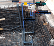
Since I already have them pipes there, why cutting? I can just connect the skimmer line to it's proper side on the skimmer, and add a "U" As should be from skimmer to the pump.
Adding a valve on the other line, that way I can block either line as I wish, I can manually place or seal the skimmer line from within the skimmer if needed or just close the valve on the other line...
I don't get it though... (looking around now...) hydraulics-wise, when water is removed from the pool doesn't it get equalized from water-level? like - spilled over to equalize?
The skimmer line is situated on water-level, I thought that if pressure is equalized in the pipes bellow water-level, when you "remove" water from the pool, to equalize it the water will be "spilled" or "sucked" from the top, the water-level, and not from the bottom where it's "static" anyways... and that's why I figured - hey the skimmer will go first anyways, the MDs are 2nd...
I don't doubt your experience!!! just my logic ... which is probably lacking... like I said, reading about hydraulics as I write this...
Also I've thought about a 4th fixing solution for this whole piping fiasco:

Since I already have them pipes there, why cutting? I can just connect the skimmer line to it's proper side on the skimmer, and add a "U" As should be from skimmer to the pump.
Adding a valve on the other line, that way I can block either line as I wish, I can manually place or seal the skimmer line from within the skimmer if needed or just close the valve on the other line...
Last edited:
- May 3, 2007
- 18,073
- Pool Size
- 20000
- Surface
- Plaster
- Chlorine
- Salt Water Generator
- SWG Type
- Hayward Aqua Rite (T-15)
The static head (water elevation) is the same for the skimmer and main drain since the water level of the spool determines that. The pressure is exactly the same for each line at the pump (with pump off). But since water is returned to the same location as where it was drawn from, static head nets out to 0 and does not affect flow rates at all.@mas985
I don't get it though... (looking around now...) hydraulics-wise, when water is removed from the pool doesn't it get equalized from water-level? like - spilled over to equalize?
The skimmer line is situated on water-level, I thought that if pressure is equalized in the pipes bellow water-level, when you "remove" water from the pool, to equalize it the water will be "spilled" or "sucked" from the top, the water-level, and not from the bottom where it's "static" anyways... and that's why I figured - hey the skimmer will go first anyways, the MDs are 2nd...
However, the dynamic head loss is different and has to do with the friction loss of the water traveling through the plumbing. Given, the large pipe size and low flow rates, friction loss should be not that much different between the MD and skimmer so flow rates from each should be about the same depending on which configuration you choose and assuming all valves are open. But that means each will get only ~50% of the total flow.
A skimmer typically requires at least 15 GPM to work properly and some as high as 25 GPM. The circulation pump you have now will struggle to deliver that even if the flow is directed 100% from the skimmer.
@mas985
That's some nifty info you deliver there!
The skimmer is 10GPM minimum and pump is rated 39 GPM, so I think it'll work the skimmer ok.
I think I'll go with what you said, 2 separate lines with a 3 way valve to connect them to the pump, have full control of it... that seems like the best solution (+You said it so it has to be )
)
probably tomorrow I'll start connecting the whole walls plumbing... I'll make some pictures as I go and when done before I cement the jets and all HOPE I won't screw it up like I almost did with the main drains...
Thanks man! You are a savior!
That's some nifty info you deliver there!
The skimmer is 10GPM minimum and pump is rated 39 GPM, so I think it'll work the skimmer ok.
I think I'll go with what you said, 2 separate lines with a 3 way valve to connect them to the pump, have full control of it... that seems like the best solution (+You said it so it has to be
probably tomorrow I'll start connecting the whole walls plumbing... I'll make some pictures as I go and when done before I cement the jets and all HOPE I won't screw it up like I almost did with the main drains...
Thanks man! You are a savior!
@mas985
Here we go...
How do I connect these "jet bodies"? I thought I can just shove a pipe in them and extend them but that doesn't seem like the case... perhaps I should create an extra hole in the pipe for that?
Or maybe they need to be placed flush with the concrete wall?
The assembly:
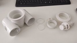
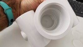
Looks like when you try to push the 50mm pipe inside it fits but it blocks the water line (the bigger hole is water right?).
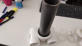
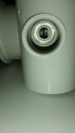
Also the threaded fitting doesn't fit the pipe for gluing:
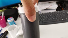
I think it should be placed inside the wall with the edge of it flush with the wall then the gasket and external fitting sits on it - right?
Here we go...
How do I connect these "jet bodies"? I thought I can just shove a pipe in them and extend them but that doesn't seem like the case... perhaps I should create an extra hole in the pipe for that?
Or maybe they need to be placed flush with the concrete wall?
The assembly:


Looks like when you try to push the 50mm pipe inside it fits but it blocks the water line (the bigger hole is water right?).


Also the threaded fitting doesn't fit the pipe for gluing:

I think it should be placed inside the wall with the edge of it flush with the wall then the gasket and external fitting sits on it - right?
@mas985
I think that in order for it to be usable I have to cut a hole in my wood construct (for the cement pouring) just enough to put it inside the wood itself, like 5mm then thigh it to the wood so it will move with it when i'm pouring cement and somehow make sure cement won't get inside of it... WHAAAA?! that's probably the wrong set i've bought...
instructions says:
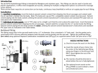
I think that just means I place it against my "woods" and that's it... deal with it once done with the cement... right? how do I make sure no cement gets inside while pouring? perhapse some silicone adhesive between the jet and the wood... that might work...
OK... AIR (big hole) is on top right?
I think that in order for it to be usable I have to cut a hole in my wood construct (for the cement pouring) just enough to put it inside the wood itself, like 5mm then thigh it to the wood so it will move with it when i'm pouring cement and somehow make sure cement won't get inside of it... WHAAAA?! that's probably the wrong set i've bought...
instructions says:

I think that just means I place it against my "woods" and that's it... deal with it once done with the cement... right? how do I make sure no cement gets inside while pouring? perhapse some silicone adhesive between the jet and the wood... that might work...
OK... AIR (big hole) is on top right?
Last edited:
- May 3, 2007
- 18,073
- Pool Size
- 20000
- Surface
- Plaster
- Chlorine
- Salt Water Generator
- SWG Type
- Hayward Aqua Rite (T-15)
These are surface mounted jets. Although they say they can be used for gunite/concrete as well, I am not sure how that would work. Are there not instructions for concrete?
I think this install might be close to what you are trying to do. The jets are wired to the rebar and the concrete surface will come to the edge of the jet but recessed by an inch or two (i.e. cupped out). Normally plaster is then used as a surface because concrete is not waterproof. I am not sure how you would do it with concrete vs gunite. Gunite does not require an inner form but concrete will unless you use a very stiff mix so that complicates things. You might get some ideas from here:
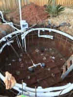
I think this install might be close to what you are trying to do. The jets are wired to the rebar and the concrete surface will come to the edge of the jet but recessed by an inch or two (i.e. cupped out). Normally plaster is then used as a surface because concrete is not waterproof. I am not sure how you would do it with concrete vs gunite. Gunite does not require an inner form but concrete will unless you use a very stiff mix so that complicates things. You might get some ideas from here:

@mas985
Hi man,
I have a new question... about the venturi air lines, what if each set of jets air line (2 jets connected to 1 line) is going out above water level? that could also work If I don't use a blower right?
There is no actual need for them to be connected to anything except reaching out above water level...
- May 3, 2007
- 18,073
- Pool Size
- 20000
- Surface
- Plaster
- Chlorine
- Salt Water Generator
- SWG Type
- Hayward Aqua Rite (T-15)
Yes, in fact some builders will put the air lines right at deck level above each jet with a cap valve so that each person can control their own jet's air level. Much like a stand alone spa.
I'll go with this first... looks like the easiest way to go... Just take the air line out next to each jet and see how that works, If not enough air or perhaps too much noise from these open air sucking holes I'll connect them to a blower on that corner where the manifold is at...Yes, in fact some builders will put the air lines right at deck level above each jet with a cap valve so that each person can control their own jet's air level. Much like a stand alone spa.
@mas985
Hi again,
thanks again and again for the input man!!! Really appreciated!
I've placed some of the jets piping today... hopefully no big mistakes... here are some images.
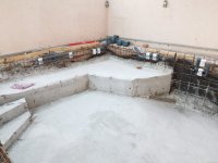
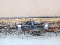
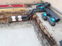
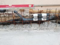
I've got a new "Issue" though...
Whats the shallowest I can place the jets? Seems like If I go with my current plan they will be situated at about 10cm bellow water level...
Questions:
1. Whats the recommended jets level for top back?
2. Will that last jet setup work?
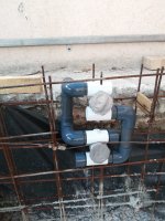
3. TOP = AIR - Bigger hole, Bottom = water - smaller hole?
(holes inside the jet body)
4. Anything else I should pay attention to?
Thanks man!
- May 3, 2007
- 18,073
- Pool Size
- 20000
- Surface
- Plaster
- Chlorine
- Salt Water Generator
- SWG Type
- Hayward Aqua Rite (T-15)
1. No set rules on that. Just where you want them.
2. It should
3. Read instructions
4. The only issue I see is that you are not pressure testing the welded joints before concrete. You are taking a huge risk. When pools are built ALL of the plumbing is installed first and fully pressure tested before any concrete or gunite is added.
2. It should
3. Read instructions
4. The only issue I see is that you are not pressure testing the welded joints before concrete. You are taking a huge risk. When pools are built ALL of the plumbing is installed first and fully pressure tested before any concrete or gunite is added.
@mas985
Holyyyyy, you are holy man! (A bit drunk after friday's night meal ... we have those... some jewish customs)
I have to have some special equipment which I don't for this whole pressure testing thing so ... I'll have to test my luck on that I guess...
What do you need for testing anyway? Maybe I can rent a compressor for air, plug my just using a pipe with a cap, although - just shoving it inside the jet and placing and end cap on it doesnt seems enough, and if I glue it then... What?!
BTW, what is a "cap valve"? Like a ball valve connected to nothing?
THanks man... now I can sleep good at night
EDIT>>>
OK, So you say we should pressure test it - then I'll test it Master!
At first I thought it's too difficult to achieve but now I don't really see why shouldn't I pressure test it... I'll finish up my jet plumbing tomorrow (most likely), connect everything including the manifold and all, put end cups on air pipes and buy some threaded plugs that fits the jets (hopefully I can find such) connect it all and then use this youtube view instruction to do the test:
I'll rent a compressor for a day, shouldn't be too expensive...
How much pressure should I test the system on? 10, 20, 30 psi?
I'm scared my jet bodies will explode
I'll probably put an update on tomorrow asking more questions etc
EDIT 2 >>>
Well I've accomplished to get 2 fittings to seal the jets (only 2 instead of 8, they don't have it around in the stores)
Now... I can do a pressure test using these 2 fittings and test the piping for each set of jets (they are in 2s anyways), but then I have to rely on the ball valves to seal the other 6 while testing...
Are the ball valves air tight? Will that test worth anything?
Thanks man.
Holyyyyy, you are holy man! (A bit drunk after friday's night meal ... we have those... some jewish customs)
I have to have some special equipment which I don't for this whole pressure testing thing so ... I'll have to test my luck on that I guess...
What do you need for testing anyway? Maybe I can rent a compressor for air, plug my just using a pipe with a cap, although - just shoving it inside the jet and placing and end cap on it doesnt seems enough, and if I glue it then... What?!
BTW, what is a "cap valve"? Like a ball valve connected to nothing?
THanks man... now I can sleep good at night
EDIT>>>
OK, So you say we should pressure test it - then I'll test it Master!
At first I thought it's too difficult to achieve but now I don't really see why shouldn't I pressure test it... I'll finish up my jet plumbing tomorrow (most likely), connect everything including the manifold and all, put end cups on air pipes and buy some threaded plugs that fits the jets (hopefully I can find such) connect it all and then use this youtube view instruction to do the test:
How much pressure should I test the system on? 10, 20, 30 psi?
I'm scared my jet bodies will explode
I'll probably put an update on tomorrow asking more questions etc
EDIT 2 >>>
Well I've accomplished to get 2 fittings to seal the jets (only 2 instead of 8, they don't have it around in the stores)
Now... I can do a pressure test using these 2 fittings and test the piping for each set of jets (they are in 2s anyways), but then I have to rely on the ball valves to seal the other 6 while testing...
Are the ball valves air tight? Will that test worth anything?
Thanks man.
Last edited:
- May 18, 2015
- 355
- Pool Size
- 28000
- Surface
- Plaster
- Chlorine
- Salt Water Generator
- SWG Type
- CircuPool RJ-60 Plus
Not sure what both ends of you plumbing look like, but have you considered the rubber expanding winterizing plugs to seal off the lines for pressure check? They come in various size ranges. If you could use them, it would provide a quick check for gross leaks.
In addition, I was watching my neighbors new pool install recently and the company doing the build pressure tested the system to 20 psi.
It sat like that for a month.
I don’t know if the rubber plugs will hold that pressure but if you have issues sourcing hard plumbing to cap things off, they may be viable for a lower pressure static test.
- May 3, 2007
- 18,073
- Pool Size
- 20000
- Surface
- Plaster
- Chlorine
- Salt Water Generator
- SWG Type
- Hayward Aqua Rite (T-15)
Pressure testing is normally done with water, not air. Just put a hose bib on the pipe and use water to pressurize. You only need about 40 psi.
@mas985Pressure testing is normally done with water, not air. Just put a hose bib on the pipe and use water to pressurize. You only need about 40 psi.
Hi,
Well, I've read a little seems like the 'avarage' hose pressure is 3-5 bars which is ~40-70 psi... I really doubt it the plumbing I've put wont hold that... And ball valves have to be water tight, otherwise what are they used for anyways...
I'll see how I can go with testing once done with the external wood frame for concrete...
Also a normal hand pump gets to a 100 psi... As it seems...
- May 18, 2015
- 355
- Pool Size
- 28000
- Surface
- Plaster
- Chlorine
- Salt Water Generator
- SWG Type
- CircuPool RJ-60 Plus
You wouldn’t go full pressure from your city water supply. The PB here used hose bib to pipe/pvc connectors. With a gauge on the setup downstream of the valve. You slowly introduce the water pressure into the system with the hose valve. Just crack the valve open a little. Get the pressure where you want it on the gauge and close the valve.
@JamesR and @mas985
Hi,
Thanks for the tip james, I was going to go full pressure...
I mean, isn't the kitchen sink tap for example getting the 'full pressure'? (Assuming everything else is closed)
I'm just using the garden hose pipe...
You wanna tell me this while thick piping and pumps and everything doesnt hold what the garden hose quick connector holds???
Here are some photos of my skimmer installed...
Didn't cut the MDs 'bad' connection from bellow... Decided to connect it anyway and just put a plug inside, that way I'll have a choice / backup for the other line...
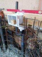
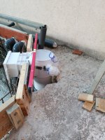
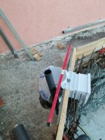
@mas985 Is there anything you can spot in there that should be fixed? Its tallest part is leveled with the wall height.
My skimmer will be only half covered in concrete as you can see the pool's wall is higher then the floor...
I'll run pressure testing today, 2 jets at a time... And start getting ready for concrete with the woods n all...
Sum:
1. Is the garden hose getting 5 bar pressure?
2. Is it OK that the skimmer is only 1/2 covered in concrete?
3. Is my skimmer plumbing/placement OK?
Thanks for everything you guys!!!
Love you @mas985 !!!
Edit:
Test done, 40 psi no leaks... I think it's ok.
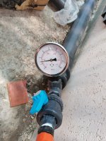
Will go on with wood work now... Hope skimmer is ok...
Hi,
Thanks for the tip james, I was going to go full pressure...
I mean, isn't the kitchen sink tap for example getting the 'full pressure'? (Assuming everything else is closed)
I'm just using the garden hose pipe...
You wanna tell me this while thick piping and pumps and everything doesnt hold what the garden hose quick connector holds???
Here are some photos of my skimmer installed...
Didn't cut the MDs 'bad' connection from bellow... Decided to connect it anyway and just put a plug inside, that way I'll have a choice / backup for the other line...


@mas985 Is there anything you can spot in there that should be fixed? Its tallest part is leveled with the wall height.
My skimmer will be only half covered in concrete as you can see the pool's wall is higher then the floor...
I'll run pressure testing today, 2 jets at a time... And start getting ready for concrete with the woods n all...
Sum:
1. Is the garden hose getting 5 bar pressure?
2. Is it OK that the skimmer is only 1/2 covered in concrete?
3. Is my skimmer plumbing/placement OK?
Thanks for everything you guys!!!
Love you @mas985 !!!
Edit:
Test done, 40 psi no leaks... I think it's ok.

Will go on with wood work now... Hope skimmer is ok...
Last edited:
- May 3, 2007
- 18,073
- Pool Size
- 20000
- Surface
- Plaster
- Chlorine
- Salt Water Generator
- SWG Type
- Hayward Aqua Rite (T-15)
Pressure testing is really for the glue joints. 5 bar is more than enough. Really 2 bar is enough.
I might try to encase the entire skimmer (except top) in concrete just for protection and to prevent leaks.
I might try to encase the entire skimmer (except top) in concrete just for protection and to prevent leaks.
Last edited:
@mas985
Hi man,
I've got them walls now.
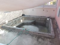
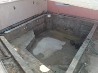
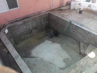
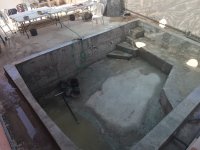
It looks OK for the most of it, pretty smooth as well...
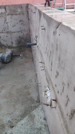
However, as you can probably spot - there are 3 major flaws that requires fixing...
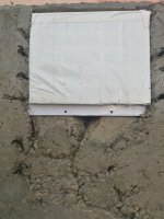
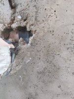
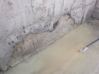
Should I wait for the concrete to cure and then fix it OR just go right ahead and do it NOW?
Can I use just plain cement + sand and water for these holes or do I need special blends and primer etc?
THANKS AGAIN AGAIN FOR YOUR HELP MAN!!!
Hi man,
I've got them walls now.


It looks OK for the most of it, pretty smooth as well...

However, as you can probably spot - there are 3 major flaws that requires fixing...


Should I wait for the concrete to cure and then fix it OR just go right ahead and do it NOW?
Can I use just plain cement + sand and water for these holes or do I need special blends and primer etc?
THANKS AGAIN AGAIN FOR YOUR HELP MAN!!!
Last edited:
Thread Status
Hello , This thread has been inactive for over 60 days. New postings here are unlikely to be seen or responded to by other members. For better visibility, consider Starting A New Thread.

