Jandy LXi 400n Fault Check IGN Control

lonniebrunet

Member
Jun 3, 2020
12
Mississauga
Hi, I've seen a few threads on this before, but mine issue seems to be a mixed bag.
I'll cover off all the issues I've had to date, and hopefully someone can help.

I inherited this pool heater when we bought the house in 2014, and I don't know how long it was used with the existing pool.

Issue 1 - 400n Fault Check IGN Control - last year
- I had this issue a few times last year, and after looking online, I cleaned the flame sensor rod and everything worked for the rest of the year

Issue 2 - turn heater on, nothing happens - last year
- Realized that the capacitor connected to the fan isn't working, and I can 'jump start" it by turning a piece with a flathead screwdriver
- Still haven't fixed this, but can jump start the fan everytime

Issue 3 - 400n Fault Check IGN Control - this year
- Cleaned the flame sensor rod - and it worked
- Then the issue came back again
- Cleaned out as much as I could inside and it on and off again works
- Up until today, if I turned off the heater and turned it back on a few times, it will eventually work
- Today not working. Don't see the flame starting through the eye hole
- On the control board I get one blinking red light after a few minutes, which I think is air flow problem

Any suggestions???
 
You need to correct issue 2! A PSC motor that is run with a weak or open (and rarely a shorted) capacitor will be running (even with a push start) outside of the rated parameters for torque, fan speed and rated amp draw. This could lead to an early failure of the motor. Depending on the age and amount of use, you could also have a problem with bearing failure on the motor. If you don't have a multimeter to check the capacitor you can just replace it as they are a fairly inexpensive part at usually under $15. Just make sure that the microfarad (mf or uf) rating is the same and the voltage rating ( usually 370 or 440 Vac ) is the same or higher. You can readily find capacitors on amazon. If you are still having problems after correcting issue 2, check back and we can troubleshoot further.
 
Hello all-

I am having the same issue with my heater. I am getting the same error on the panel. The fan/blower is not starting when I turn on the heater. I replaced the capacitor and that did not work, the voltages check out according the troubleshooting guide. My main question is, does the fan/blower kick off the whole process for starting the heater? If the voltages check out, is there something else that kicks off the fan/blower to start? My next step is to remove the fan/blower and bench test it. What are all of the different wires? Is one of them a switching wire? Any help would be appreciated.

Jandy LXi 250
6 years old
 
Last edited:
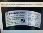
Initially to start your heater the pump must be running to close the water pressure switch and your temperature must be set above the current water temperature. At that point the controls will try to start the blower motor. Is your heater wired for 120Vac or 240Vac? Where are you checking for voltage to the motor? Does this photo look like the label on the blower motor?
 

Attachments

  • IMG_1355.JPG
    IMG_1355.JPG
    671.5 KB · Views: 5
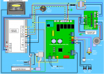
@swamprat69 Thanks for the quick response! It is wired for 120Vac. I followed the troubleshooting guide and measured the voltage between F2 terminal of Ignition Control and ground (A) which checked out. Also voltage between F1 terminal of Ignition Control and ground (A) which was good and voltage between Blue (L) wire to Blower on PDB and ground (A). The heater does have a Chikee motor. Same model # as your picture.

lxi.PNG
 
I am not seeing any troubleshooting guide in the manual that I am looking at that is telling me to measure voltages at the ignition control for "Fault check ign control". If the controls are asking for the blower to start you should have 120Vac between white and blue/black on the power distribution board where the blower motor is connected to the power distribution board
 
If you pull the motor plug from the PDB and measure ohms between the white plug wire and the blue plug wire you should get a reading of the windings. If it reads open then the motor winding is bad. Also when you say your readings are "good", it really doesn't tell me anything as that is not a meter reading.
 

Enjoying this content?

Support TFP with a donation.

Give Support
@swamprat69 Here is a link to the troubleshooting guide I was using. Per your instructions, I am not getting 120Vac between the white and blue or back wires on the PDB. They measure around 15V and go up slightly when I turn the heater on. I am also not getting 24v between the W and GND on the ignition control board. Let me know next steps. Thanks!

 
Sounds like your motor windings are good. Are you getting 24V between GND on the ignition control and 24V on the ignition control? If "yes" are you getting 24V between GND on the ignition control and wire 10 on the J3 socket? Are you getting 0 volts between wire 5 and wire 4 on the J15 socket?
 
Wire 4 on J15 socket is power in to water pressure switch. Wire 5 on J15 socket is power out of water pressure switch. You should have 24V to IC Gnd on both wires if the water pressure switch is closed. If you do, the next thing that happens is the PIB looks at the reading from the water temperaure sensor and if it is lower than the setting that you have set on your user interface it sends 24V to wire 10 on J3 and also to W on IC. Since that is not happening, you might have a problem with the water temperature sensor, PIB or user interface. I am not familiar with the Jandy water temperature sensor and don't know for sure if it is a 10K ohm thermister. If it is a 10K ohm thermister the chart below should give you the ohm reading at the temperature of your pool water now if you disconnect the water temperature sensor from the board and measure the resistance in ohms.
 

Attachments

  • TempVsResistChart.pdf
    11.4 KB · Views: 2
I get 24V on wire 4 and wire 5 on the J15 socket. The Water thermister measures around 8,300 ohms and the water temp is 84 degress so that looks correct. Is it possible that the blower/motor is not working even though the motor windings are measuring resistance? There is an LED on the ignition control that does not light up. Could it be that it is bad since i am not getting 24v between the W and GND on the ignition control board?
 
Doubtful that it is the ignition board as it wouldn't do anything until it sees 24V at the "W" terminal on the board. More likely a problem with the user interface or the power interface board. You could try jumping 24V hot from the red #3 wire or "24VAC" on the IC to "W" on the IC to see if that would start the heater. If it does , you could try gently tapping on what I assume are relays (the black rectangles on the PIB) to see if they are stuck. You could also examine the back of the PIB and user interface (with the power off) for any cracked traces and any blackening or browning of the board (signs of a short or overheating).
 
Jumping Red#3 to the W on the IC worked! I held it here and the heater went through the motions and fired. I looked at the back of the PIB and the UI and did not see any blackening or browning or any cold solders. Tapping the relays didn't do anything. When I start it, I do hear a clicking noise but there are multiple relays on the PIB. Thoughts?
 
You might have a relay problem, but it might also be a problem with the electronics on either the user interface or the PIB. At this point I would be a little out of my comfort area without knowing the operating sequences and specs on the circuit boards.
 
Last edited:

Enjoying this content?

Support TFP with a donation.

Give Support
Thread Status
Hello , This thread has been inactive for over 60 days. New postings here are unlikely to be seen or responded to by other members. For better visibility, consider Starting A New Thread.