Test indicate power is getting to Aquarite Goldline AQR15, but LED on Display Board indicates no power. Test shows no electricity in red, black & orange wires between Main Display Board & terminals on the back of the box. The one yellow wire between the transformer & a terminal at the back of the box also shows no current, but the other yellow wire between the transformer and the Main Display Board shows current. Have replaced Display Panel, but no change. So . . . do I need to replace the entire Main Display Board? The transformer? The fuse? Or all of the above? Suggestions about how I should proceed most welcome.

Circuit Board Aquarite Goldline SWG
- Thread starter Henry M
- Start date
You are using an out of date browser. It may not display this or other websites correctly.
You should upgrade or use an alternative browser.
You should upgrade or use an alternative browser.
- Jul 21, 2013
- 65,604
- Pool Size
- 35000
- Surface
- Plaster
- Chlorine
- Salt Water Generator
- SWG Type
- Pentair Intellichlor IC-60
Thanks for your reply. Test on fuse indicates an electrical current. I'm assuming that means it is functioning as it should. Am at a loss as to what to do next.
What is the supply voltage and how are you measuring it?
Does the display show anything?
 www.troublefreepool.com
Does the display show anything?
Hayward Aquarite SWG - Further Reading
www.troublefreepool.com
Last edited:
superuser
Well-known member
How are you testing? Your messages make it sound like you're probing around with one of those contactless voltage detectors or something.
Thanks for your reply. Voltage supply is 220. Display Panel is new, but it is just as blank as the older one.What is the supply voltage and how are you measuring it?
Does the display show anything?
Hayward Aquarite SWG - Further Reading
Am testing with a voltage detector that does make contact with wires & terminals. It just indicates whether there is voltage present; does not indicate how much.How are you testing? Your messages make it sound like you're probing around with one of those contactless voltage detectors or something.
superuser
Well-known member
Unfortunately that's not going to tell you much, and thus won't really help with your diagnosis. It goes without saying, but I'll say it anyway, probing around high voltages without knowing what you're doing can be uncomfortable, hair raising, even deadly. So that out of the way, you're going to need some other test equipment if you want to diagnose this yourself. A simple multimeter will do a lot to help you figure things out.
If you can buy or borrow a meter, you can do some quick simple checks for the more obvious things. First, turn off the power to your entire setup so you don't mess anything up. Use the continuity check on the fuses to make sure they're good. Then do continuity checks on the connections, make sure all the connectors and wires are good. If it goes beyond that, it gets really tricky, really fast.
If you can buy or borrow a meter, you can do some quick simple checks for the more obvious things. First, turn off the power to your entire setup so you don't mess anything up. Use the continuity check on the fuses to make sure they're good. Then do continuity checks on the connections, make sure all the connectors and wires are good. If it goes beyond that, it gets really tricky, really fast.
Thanks for the advice. Electricity does scare the bejesus out of me, and I am very tentative when having to deal with it. Using a multimeter seems like a sound idea & I will do that tomorrow. When you mention fuses, are you referring to the one that is on the Main Circuit Board? Are there other fuses elsewhere I should check? Am trying to avoid having to buy an entirely new Main Circuit Board and/or transformer. Would be wonderful if replacing a fuse fixes the entire problem. Again, many thanks for taking the time to advise a novice like me.Unfortunately that's not going to tell you much, and thus won't really help with your diagnosis. It goes without saying, but I'll say it anyway, probing around high voltages without knowing what you're doing can be uncomfortable, hair raising, even deadly. So that out of the way, you're going to need some other test equipment if you want to diagnose this yourself. A simple multimeter will do a lot to help you figure things out.
If you can buy or borrow a meter, you can do some quick simple checks for the more obvious things. First, turn off the power to your entire setup so you don't mess anything up. Use the continuity check on the fuses to make sure they're good. Then do continuity checks on the connections, make sure all the connectors and wires are good. If it goes beyond that, it gets really tricky, really fast.
superuser
Well-known member
I'm not familiar with the unit you're trying to troubleshoot, to be frank I've only been a pool owner for a month, but I'll try to walk you through some basic/universal electronics troubleshooting the best I can.
One of the biggest lessons I learned young, is always start simple. That led into the next lesson that a lot of failures have simple causes and simple solutions. It's easy to go too deep and skip over the problem entirely. That said, you'll need to take everything I say with regards to your specific unit with a grain of salt since I've never seen one before. You state you have power between the units, but the power indicator (LED?) is not turning on. That indicates you probably have high voltage (110V/220VAC) but no low voltage (5VDC, maybe?). Since electricity has to make a full round trip to do any work, we're looking for any potential break in the loop. The fuses provide a link in that chain that can easily be broken. A word of caution though, fuses don't blow for no reason - if you find a blown fuse, and replacing it doesn't fix the problem (e.g. it blows again), there's additional troubles to be found. But, lets start there. Grab a multimeter, and set it for continuity. Most will have a mode where touching the probes (and completing the loop through the meter) causes it to beep. If we then touch the leads to either side of the fuse and it beeps, the fuse is good. Check all the fuses. If they all test good, you may need to remove the fuse from its holder and test to make sure. If the fuse is protecting a transformer for example, it may still beep.
If none of the fuses are blown, it's time to move to the next item but for that I'd need a look inside at what you're seeing. If you can post a photo or two I can try to help. We can check connections, and if those look good we can move to trying to identify the various sections of the unit and try to see if the power supplies are doing what they're supposed to.
Thank you!!! Will be touch, probably tomorrow.I'm not familiar with the unit you're trying to troubleshoot, to be frank I've only been a pool owner for a month, but I'll try to walk you through some basic/universal electronics troubleshooting the best I can.
One of the biggest lessons I learned young, is always start simple. That led into the next lesson that a lot of failures have simple causes and simple solutions. It's easy to go too deep and skip over the problem entirely. That said, you'll need to take everything I say with regards to your specific unit with a grain of salt since I've never seen one before. You state you have power between the units, but the power indicator (LED?) is not turning on. That indicates you probably have high voltage (110V/220VAC) but no low voltage (5VDC, maybe?). Since electricity has to make a full round trip to do any work, we're looking for any potential break in the loop. The fuses provide a link in that chain that can easily be broken. A word of caution though, fuses don't blow for no reason - if you find a blown fuse, and replacing it doesn't fix the problem (e.g. it blows again), there's additional troubles to be found. But, lets start there. Grab a multimeter, and set it for continuity. Most will have a mode where touching the probes (and completing the loop through the meter) causes it to beep. If we then touch the leads to either side of the fuse and it beeps, the fuse is good. Check all the fuses. If they all test good, you may need to remove the fuse from its holder and test to make sure. If the fuse is protecting a transformer for example, it may still beep.
If none of the fuses are blown, it's time to move to the next item but for that I'd need a look inside at what you're seeing. If you can post a photo or two I can try to help. We can check connections, and if those look good we can move to trying to identify the various sections of the unit and try to see if the power supplies are doing what they're supposed to.
On an Aquarite the first thing you need to check is the thermistor if you haven't already. That's the number one part that fails on those units. The article that JamesW linked to has a good testing procedure for those units.
Many, many thanks!! This is a whole new learning experience for me; not unlike learning a foreign language. While I'm not certain I grasp it all, the information you provided will only help, I'm sure. I will take this slow & carefull; will post results. TFP people like you are a godsend to novices like me. Am glad to be a Member, and thankful our paths cross.On an Aquarite the first thing you need to check is the thermistor if you haven't already. That's the number one part that fails on those units. The article that JamesW linked to has a good testing procedure for those units.
Orion7319
Bronze Supporter
- Jul 1, 2020
- 1,442
- Pool Size
- 19775
- Surface
- Vinyl
- Chlorine
- Salt Water Generator
- SWG Type
- Hayward Aqua Rite (T-15)
superuser
Well-known member
Ordered model AS32 2RO25 new thermistor. Turns out the gauge of the contact "legs" are too flat, wide & spaced too far apart to fit onto my Main Circuit Board. The gauge of the contact legs on the old termistor are thin. When I cut off the old termistor, I left the existing legs & tried to solder the new model onto them. Didn't work well. Have very little left of the original legs that are attached to the Board. So . . . . am wondering if I should try another model thermistor. Space to solder another one is limited. Or do I need to order a whole, new Main Circuit Board?
SL32 2R025 Ametherm | Circuit Protection | DigiKey
Order today, ships today. SL32 2R025 – Inrush Current Limiter 2 Ohms ±20% 25 A 1.220" (31.00mm) from Ametherm. Pricing and Availability on millions of electronic components from Digi-Key Electronics.
This is the original one. I find it easier to work with.
Remove the old legs and use a desoldering pump to get the old solder out of the way and then install the new thermistor.
C0d3Sp4c3
Well-known member
- Dec 10, 2018
- 333
- Pool Size
- 20000
- Surface
- Plaster
- Chlorine
- Salt Water Generator
- SWG Type
- Hayward Aqua Rite (T-15)
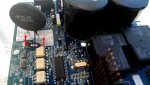
For the Aquarite, the thermistor solder lands are larger and peppered with vias to absorb the heat. AFAIK, the pads can accommodate either SL32 or AS32 series Thermistors. If your pcb is similar to the attached pic, you can replace the existing SL32 with the AS32. You need to use a 30-40 watts soldering iron and solder wick to remove the old solder from the plated through hole to mount the AS32.
Attachments
Thread Status
Hello , This thread has been inactive for over 60 days. New postings here are unlikely to be seen or responded to by other members. For better visibility, consider Starting A New Thread.