What size breaker feeds that box from the main panel?
I will have to check when I get home tomorrow.
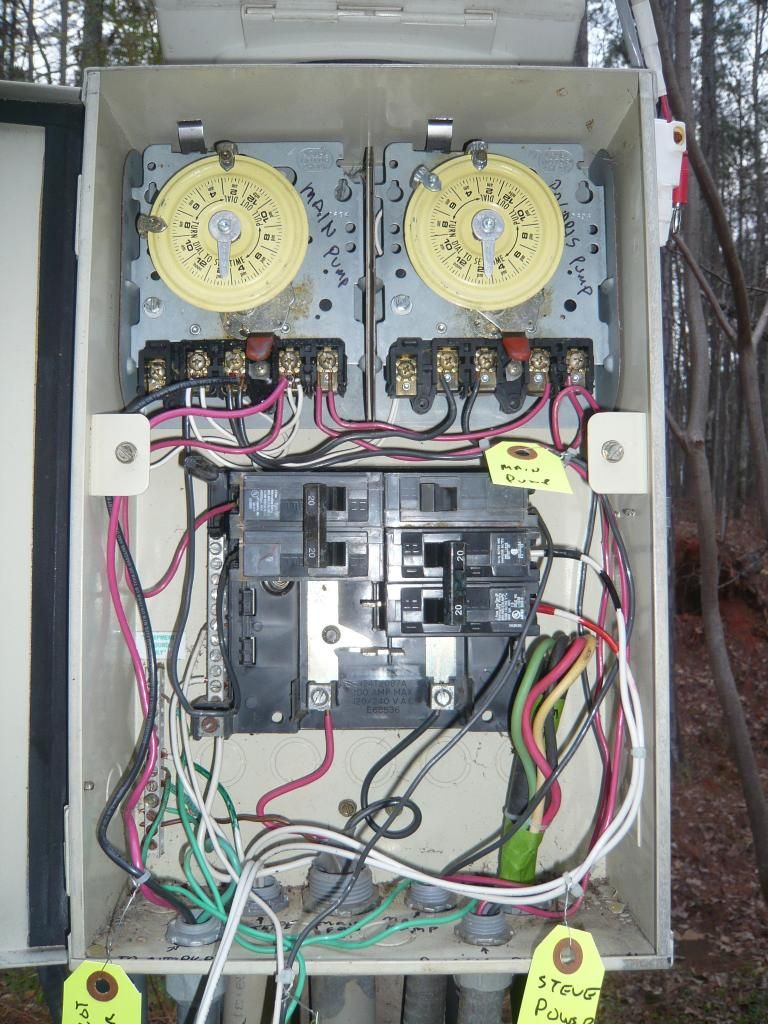
I am a bit curious about the abandoned cable in the lower right hand side.
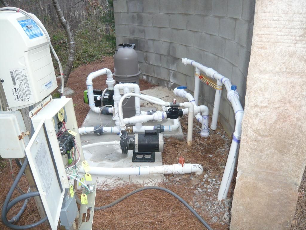
I did this temporarily just to work on the system and ID the wires and clean it up. It is a freeze guard.
That looks like it may have been the original feed based on the wire size. The wire feeding it now looks to be a bit small.
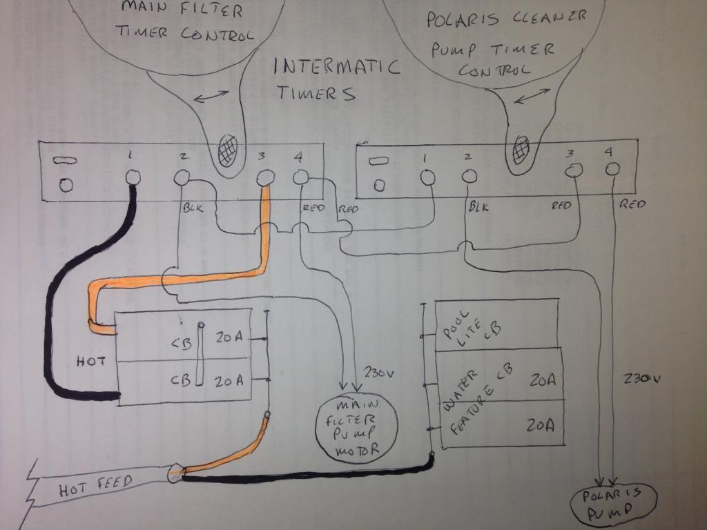
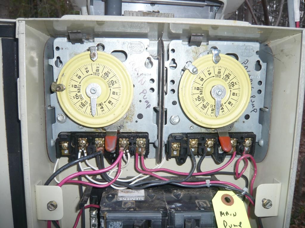
Not real sure what the smaller white wires are doing on the terminals of the left hand timer. Kind of hard to trace them. It may be they are the power feeds to the timer motors.
I am a bit concerned about what type of wire was used coming in and out of the box. My concern comes from the fact that two white wires were repurposed as hot leads. The way they are used is to code as they are marked. I am more concerned that they most likely come from romex type cable. If this is the case it must be rated for direct burial (uf-b)even if it is in pipe as NM is not rated for wet locations.
not sure here... prob is not up to code...I know the white wires are in conduit.
What do the wires go to that hang out of the front of the box?...To a water feature
As far as everything else, It looks pretty good. A little sloppier than I would like, but still functional.
Your drawing looks fine. But in the picture I see a pair of red and black wires that are not in the drawing that are hooked to the timer on the left. Looks like the Red is always powered from one leg and the Black is powered from the other leg when the switch is on.
Ideally you would have the pump supplied by a GFCI breaker, but with those added wires going to different loads (?) that could cause an imbalance and trigger a GFCI.
Is there a GFCI somewhere on the light circuit at least???? I have my light circuit feed a GFCI outlet and then off the protected side of the outlet to my light ... maybe yours is the same?
Good catch. The bus bars are not correct in the drawing ... everything after the breakers looks fine though.
I think the new codes require a GFCI breaker on the pumps. That SWG wiring seems odd to me that one leg is always hot and the other is switched.
Where I live it is illegal for any pool technician to touch a pool that doesn't have GFCI breakers on everything electrical within 15 feet of the pool. So you can have a non-GFCI pump, but you can't have it serviced.
Not sure I will be able to help here since I do not know how these systems work.
I will say that the SWG should run fine with the pump on low. Mine does.
The Autopilot guy says it needs 15 GPM minimum flow...any idea what low is???
I have never seen a 2-speed motor with a digital timer ... this may actually cause you problems in that it may not allow you to wire the low and high speed separately to be controlled by the SWG or another timer. And if you are going to allow some other timer to control it, why have an electronic timer on the motor in the first place?
Using the AutoPilot to control high/low speed might not even be possible with that pump controller, and even if it is possible, ...so how do you suggest I run the system?
...it isn't very much use.
Generally you want the pump on low speed all of the time and only switch it to high speed when vacuuming or backwashing....wow did not know this. I assumed one would run it on high for at least a few hours a day in the heat of summer...