Tell me more about the purge timer. I think I wanna add one to my install.
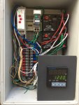
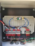
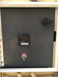
I started by removing the original Hotspot Junction box, as I rebuilt the functions of what I wanted for controls, I ended up with almost nothing in the new Hotspot Junction box, as most items are in the Easytouch cabinet and then a few items at the Condenser Junction.
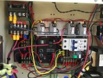
See GRT8-M2 Purge Timer Relay, and ICM104 Compressor delay Timer below
TB1 - 24VAC Terminal Block
1 = Not Used
2 = EasyTouch 24VAC – Blue- To Hotspot Junction Box
3 = Not Used
4 = EasyTouch 24VAC Common – White – To Hotspot Junction Box
TB2 - 24VDC Terminal Block
1 & 2 = EasyTouch 24VDC Positive – Red- To; Both 115V Pump Relays, Hotspot Junction Box, ECS30AC Current Sensor Relay (two wires), and Two RIBXKTA Current Sensing Relays (Chlorinator Control)
3 = Not Used
4 = Easytouch 24VDC Negative – Black - ??????
TB3 - Pump Control Terminal Block
1 = Red - EasyTouch Motherboard “(Low Pump) Pump J8 negative pin” thru IN4002 Diode to terminal 2. (Logic - 24VDC Negative = Pump On)
2 = Red - Low Speed Pump out to “Pump Fail Safe” Relay base terminal 41
3 = Red - Hotspot Low Cool from Condenser Junction “Purge Timer” thru IN4002 Diode to terminal 2. (Logic - 24VDC Negative = Pump On)
4 = Green - EasyTouch Motherboard “(High Pump) Aux 1, J9 negative pin” thru IN4002 Diode to terminal 5 (Logic - 24VDC Negative = Pump On)
5 = Green - High Speed Pump out to “Pump Fail Safe” Relay base terminal 31
6 = Green - Hotspot High Cool from Condenser Junction, “High Cool Relay” thru IN4002 Diode to terminal 2. (Logic - 24VDC Negative = Pump On)
TB4 - Hotspot Junction Box Terminal Block
1 = EasyTouch 24VAC – Blue
2 = EasyTouch 24VAC Common – White
3 = EasyTouch 24VDC Positive – Red
4 = EasyTouch 24VDC Negative – Black
5 = Low Cool from Condenser Junction Box - Orange
6 = High Cool from Condenser Junction Box – Green
7 = Hotspot Pump Current Sensing to “Pump Fail Safe” Relay base terminal 21 – Yellow
8 = Hotspot Pump Current Sensing return, 24VAC from RIBXKTA Current Sensing Relays - Brown
9 = Not Used
10 = Switched 24VDC Negative to Condenser Junction Box – Black
11 = Flow switch (P/N GLX-FLO-RP) – Yellow
12 = Switched 24VAC to Condenser Junction Box – Blue
TB5 - Hotspot Junction Box Temperature Sensor Terminal Block
1 = PT100 Positive
2 = PT100 Negative
3 = PT100 Negative
TB6 – HeatExchanger Junction Box Terminal Block
TB7 - HeatExchanger Junction Box Terminal Block
1 = PT100 Positive
2 = PT100 Negative
3 = PT100 Negative
To; P/N = T-PRO RTD “PT100 Temperature Sensor – Probe 4×30MM”
TB8 – Condenser Junction Box Terminal Block
1 = Airhandler 24VAC “Low Cool” – Red – To; GRT8-M2 Low Pump and Hotspot Enable Purge Timer Relay, and ICM104 Timer.
2 = Airhandler 24VAC “High Cool” – Green – To; High Pump Enable Relay, and ICM104 Timer.
3 = Airhandler 24VAC Fused – Blue - To ITC-106RL Temp Controller, and GRT8-M2 Purge Timer.
4 & 5 – Airhandler 24VAC Common – White – Switched by ITC-106RL Temp Controller at set “Liquid Line Temperature” to provide fan or pump fail safe.
6 = EasyTouch 24VDC Negative switched at Hotspot Junction – Black - To; Purge Timer and High Pump relays.
7 = EasyTouch 24VAC (Controlled by; Power Switch, ITC-106RL Hotspot Temp Controller, Pump Current Sensors, and Flow Switch/Relay) – Blue - Thru Purge Timer to Hotspot Freon Valves and Fan Disconnect Relay.
8 = EasyTouch 24VAC Common – White - To Hotspot Freon Valves and Fan Disconnect Relay.
9 = EasyTouch 24VDC Positive – Red – Future use.
10 = EasyTouch 24VDC Negative – Black – Future use.
11 = Low Pump Enable – Yellow – From Purge Timer.
12 = High Pump Enable – Green – From High Pump Enable Relay.


