Hotspot FPH AC heat reclamation pool heater - a review!

Thank you guys for all the help. So far the hardest part to find is the pump out flow resistor. Any ideas where to find it ? Also a few of you installed a flow sensor cutoff. Which flow sensor to use ? How did you install it and where does it connect to the FPH controller ?

The water flow switch I use is P/N GLX-FLO-RP
The flow switch is installed after the heat exchanger and controls a relay, which opens and closes the AC wire to the three hotspot devices at the condenser (Switch over / 3 way valve, recovery valve and fan bypass relay)

The recovery Flow restrictor is a A/C supply house item, call hotspot for part numbers...
 
Different start sequence. Currently, the way FPH controller works is that when the house thermostat calls for for cooling, outside unit starts the usual way, the controller turns on the pool pump and samples water temperature for 25 seconds, then if water temperature is below set point, turns on the heat reclaim valve to circuit refrigerant through the water cooled exchanger and turns off the fan. IMO, there are few problems with this : heat is wasted for 25 seconds, fan turns on and off unnecessarily, and the biggest problem is the valve changing the direction of refrigerant while compressor is on can cause liquid hammer and potentially damage the compressor.
I propose this sequence. House thermostat call for cooling starts pool pump and energizes the heat reclaim valve coil and solenoid coil and turns off fan but does not start the compressor. FPH controller samples water temperature for 25 seconds, if pool needs heat, starts the compressor, if not de-energizes heat reclaim valve coil and solenoid coil and starts compressor with fan and turns pool pump off.
 
  • Like
Reactions: newpoolj
Different start sequence. Currently, the way FPH controller works is that when the house thermostat calls for for cooling, outside unit starts the usual way, the controller turns on the pool pump and samples water temperature for 25 seconds, then if water temperature is below set point, turns on the heat reclaim valve to circuit refrigerant through the water cooled exchanger and turns off the fan. IMO, there are few problems with this : heat is wasted for 25 seconds, fan turns on and off unnecessarily, and the biggest problem is the valve changing the direction of refrigerant while compressor is on can cause liquid hammer and potentially damage the compressor.
I propose this sequence. House thermostat call for cooling starts pool pump and energizes the heat reclaim valve coil and solenoid coil and turns off fan but does not start the compressor. FPH controller samples water temperature for 25 seconds, if pool needs heat, starts the compressor, if not de-energizes heat reclaim valve coil and solenoid coil and starts compressor with fan and turns pool pump off.
Makes good sense. Anyone reached out to Hotspot?
 
  • Like
Reactions: newpoolj
I added a "Purge Timer" to my installation. I noticed that most all my A/C use (Mostly at night) the compressor(s) are called for in cycles with less then 15 minutes between cycles. I don't mind the compressors cycling because they must, but I prefer to keep the pump(s) and Hotspot valves engaged during those 15 minutes of compressor off cycle. It was to accomplish a couple of things;
1) Needless cycling of hotspot valves,
2) Freon moving back to air side when valves release,
3) Purging of latent heat in the exchanger,
4) Ichem requires a 15 minutes pause at startup (Which also pauses intellichlor), so "Purge Timer" keeps chemicals at steady state.

Also added adjustable compressor timers, so that hotspot system could be running before compressors started.
Tell me more about the purge timer. I think I wanna add one to my install.
 
Tell me more about the purge timer. I think I wanna add one to my install.

I started by removing the original Hotspot Junction box, as I rebuilt the functions of what I wanted for controls, I ended up with almost nothing in the new Hotspot Junction box, as most items are in the Easytouch cabinet and then a few items at the Condenser Junction.

See GRT8-M2 Purge Timer Relay, and ICM104 Compressor delay Timer below

TB1 - 24VAC Terminal Block
1 = Not Used
2 = EasyTouch 24VAC – Blue- To Hotspot Junction Box
3 = Not Used
4 = EasyTouch 24VAC Common – White – To Hotspot Junction Box

TB2 - 24VDC Terminal Block
1 & 2 = EasyTouch 24VDC Positive – Red- To; Both 115V Pump Relays, Hotspot Junction Box, ECS30AC Current Sensor Relay (two wires), and Two RIBXKTA Current Sensing Relays (Chlorinator Control)
3 = Not Used
4 = Easytouch 24VDC Negative – Black - ??????

TB3 - Pump Control Terminal Block
1 = Red - EasyTouch Motherboard “(Low Pump) Pump J8 negative pin” thru IN4002 Diode to terminal 2. (Logic - 24VDC Negative = Pump On)
2 = Red - Low Speed Pump out to “Pump Fail Safe” Relay base terminal 41
3 = Red - Hotspot Low Cool from Condenser Junction “Purge Timer” thru IN4002 Diode to terminal 2. (Logic - 24VDC Negative = Pump On)
4 = Green - EasyTouch Motherboard “(High Pump) Aux 1, J9 negative pin” thru IN4002 Diode to terminal 5 (Logic - 24VDC Negative = Pump On)
5 = Green - High Speed Pump out to “Pump Fail Safe” Relay base terminal 31
6 = Green - Hotspot High Cool from Condenser Junction, “High Cool Relay” thru IN4002 Diode to terminal 2. (Logic - 24VDC Negative = Pump On)

TB4 - Hotspot Junction Box Terminal Block
1 = EasyTouch 24VAC – Blue
2 = EasyTouch 24VAC Common – White
3 = EasyTouch 24VDC Positive – Red
4 = EasyTouch 24VDC Negative – Black
5 = Low Cool from Condenser Junction Box - Orange
6 = High Cool from Condenser Junction Box – Green
7 = Hotspot Pump Current Sensing to “Pump Fail Safe” Relay base terminal 21 – Yellow
8 = Hotspot Pump Current Sensing return, 24VAC from RIBXKTA Current Sensing Relays - Brown
9 = Not Used
10 = Switched 24VDC Negative to Condenser Junction Box – Black
11 = Flow switch (P/N GLX-FLO-RP) – Yellow
12 = Switched 24VAC to Condenser Junction Box – Blue

TB5 - Hotspot Junction Box Temperature Sensor Terminal Block
1 = PT100 Positive
2 = PT100 Negative
3 = PT100 Negative

TB6 – HeatExchanger Junction Box Terminal Block


TB7 - HeatExchanger Junction Box Terminal Block
1 = PT100 Positive
2 = PT100 Negative
3 = PT100 Negative
To; P/N = T-PRO RTD “PT100 Temperature Sensor – Probe 4×30MM”


TB8 – Condenser Junction Box Terminal Block
1 = Airhandler 24VAC “Low Cool” – Red – To; GRT8-M2 Low Pump and Hotspot Enable Purge Timer Relay, and ICM104 Timer.
2 = Airhandler 24VAC “High Cool” – Green – To; High Pump Enable Relay, and ICM104 Timer.
3 = Airhandler 24VAC Fused – Blue - To ITC-106RL Temp Controller, and GRT8-M2 Purge Timer.
4 & 5 – Airhandler 24VAC Common – White – Switched by ITC-106RL Temp Controller at set “Liquid Line Temperature” to provide fan or pump fail safe.
6 = EasyTouch 24VDC Negative switched at Hotspot Junction – Black - To; Purge Timer and High Pump relays.
7 = EasyTouch 24VAC (Controlled by; Power Switch, ITC-106RL Hotspot Temp Controller, Pump Current Sensors, and Flow Switch/Relay) – Blue - Thru Purge Timer to Hotspot Freon Valves and Fan Disconnect Relay.
8 = EasyTouch 24VAC Common – White - To Hotspot Freon Valves and Fan Disconnect Relay.
9 = EasyTouch 24VDC Positive – Red – Future use.
10 = EasyTouch 24VDC Negative – Black – Future use.
11 = Low Pump Enable – Yellow – From Purge Timer.
12 = High Pump Enable – Green – From High Pump Enable Relay.
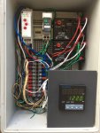
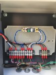
Condenser Junction.JPGHotspot Junction.JPGHotspot Controller.JPGEasytouch Junction.JPG
 
  • Like
Reactions: duade
I am confused why the system needs to be so complex. Why not just part 1 (blue heat exchanger)? Why is there a need for the second part which adds complexity, failure points, and cost to the system. I would prefer to use just the heat exchanger to pre-cool the refrigerator and let the ac system work normally without shutting part of it down. I must be missing something here. What is wrong with this proposal:

1. Connect blue heat exchanger in front of and inline with the outdoor condensor unit.
2. Connect plumbing to pool.
3. Install jandy valve with actuator to divert water into or bypass blue heat exchanger.
4. Tell Jandy (or another controller) to close the valve when the temperature is satisfied.
5. Done. Do not install 3-way valve on refrigerant line. Do not install another controller. Do not interrupt normal condenser fan operation.

Wouldn't this basically accomplish the same thing? When heat is needed to the pool, water goes through the system heating the pool and pre-cooling the refrigerant before it gets to the outdoor unit where things work as normal (the condenser is the second method of cooling)... when the pool is satisfied, the water stops flowing and the cooling is done only with the outdoor condenser fan as it always did before installing the heat exchanger.

Blue Heat Exchanger: $495 (Aliexpress.com : Buy Free shipping ! 29.0KW tube heat exchanger for swimming pool best selling products from Reliable exchange application suppliers on Refrigeration Equipment High Quality)

Install: Much less because it is much less complicated.

Total: $1,500 maybe?

I understand that because the AC condenser fan is also cooling, I am losing some heat to the atmosphere but in turn using both is putting less stress on my compressor.

The only other downside I could see is that possibly the stagnant water inside the blue heat exchanger warms up to unacceptable temperatures (up to 225?) without water flowing through but that does not seem likely at all.

Thoughts?

(Approved by Jim R. 1/10/2018...)

This is my thought as well. Is there a problem with having two condensers in series? The hot gas would come off the compressor, go through the water cooled condenser, then go through the air cooled condenser, then the accumulator, then head to the evaporator as a liquid. It seems like it would just unload the compressor that much more. Is there such a thing as too much subcooling?

Part of the way that A/C manufacturers have been improving efficiency is by increasing the size of the condenser coils. Can you go so far as to essentially double the condenser coil capacity without causing oil return, or other unforeseen problems?

Would love to hear what swamprat69 has to say on this.

Thanks.
 
I specifically asked Hotspot about just installing the water exchanger before the air exchanger, and operate as one. (because I had to build the "Balance Coil" for the water side twice.)

The answer was the point at which the freon becomes liquid in the coils. This should be the same for both and and water cooled modes. How do you know if they are the same? by the operating pressures.

If you put one in front of the other the system charge level will change with each mode...

In the scenario I'm thinking of, there would be no switching of modes. The refrigerant would always flow through both condensers.
 
In the scenario I'm thinking of, there would be no switching of modes. The refrigerant would always flow through both condensers.

Are you not going to be able to stop heating heating the pool, by not circulating water thru the water exchanger? No pump down time or pool draining ??

You would be switching modes, by which half of the (Now double) condensing coil is cooling the freon, water or air. Which mode do you charge the system for? Water and then be over charged when using air, or charge the system for air cooling and be under charged with heating the pool??

That is why the tubing added after the heat exchanger is called the "Balance coil", because it is balancing the system to have the same charge level in either mode.
 
Last edited:

Enjoying this content?

Support TFP with a donation.

Give Support
I run my pump continuously anyways, so the FPH would always have flow. Even if it didn't have water flow, it would essentially just be a pipe with a water jacket around it and the air cooled condenser would have to do all of the heat rejection, which it is already sized to do.

The refrigerant charge would have to be increased because of the added volume of the FPH, but it would be a constant charge during operation. The refrigerant would be filling the same exact volume, whether or not there is water flow through the FPH. You only have to worry about charge balance if you are isolating the different condensers during different modes. I am proposing to eliminate the 3-way valve and added controls entirely, so that the refrigerant path never changes. This would be much simpler.
 
Yes there is such a thing as "too much" subcooling. I have been loosely following this thread for a couple months, but without more detailed engineering specifics regarding the FPH system it is difficult to answer many of the questions that I have. I had 2 1/2 years towards an Engineering degree when I was interupted by Vietnam. When I returned, I found myself unable to work in a closed enviroment or with multiple people at the same time and switched to HVAC/Refrigeration service/repair. It is difficult to evaluate/diagnose a system without knowing all of design parameters and actual operating measurements. Normal subcooling is usually in the 10-12 degree range which allows for pressure loss when the evaporator is above the condenser due to liquid line rise while maintaining a solid liquid column to the metering device. Excessive subcooling ( depending on the system design normally > 15-20 degrees ) can result in not all of the liquid refrigerant in the evaporator being turned into the gaseous state and liquid slugging of the compressor. The compressor is only meant to pump gas and can be damaged if liquid is present. Heat pumps because of the size mismatch when running the system in reverse will normally have a suction accumulator between the evaporator and the compressor to prevent liquid slugging to the compressor. It appears that FPH is trying to match AC condenser volume with FPH volume in order to maintain constant system high side volumetric charge. What is difficult to tell is how FPH tries to maintain normal system operating pressures/temperatures as there has to be a difference in heat transfer of the condensers between the AC aluminum condenser and the FPH ( solid titanium or titanium coated??? ) condenser. I have previously seen in this thread ( not exactly sure where due to length of the thread ) that a normal high side pressure of > 200 psi was dropped to 100 psi when the FPH side of the system was in use, but system subcooling was not stated? Like I said, difficult to give a definitive answer without all of the information.
 
  • Like
Reactions: chillermonster
I *think* that the FPH is sized to roughly match the heat transfer capacity of the air cooled condenser. In instances where the FPH has slightly more capacity, you get decreased high side pressure, although 100 PSI less is somewhat suspect.

I am thinking that by throttling the water flow, I could limit the subcooling to avoid slugging the compressor. I am also thinking that the air cooled condenser isn't going to provide much heat transfer on hot days if it is downstream of the water cooled condenser. The refrigerant and ambient temperatures would start to approach one another to the point that no heat would move. In practice, I think this looks like full water flow on hot days and possibly a reduced flow on cooler ambient days.

My particular installation would be on a Goodman 2.5 ton straight air (not heat pump) unit that serves my upstairs. The evaporator is in the attic, so it is about 25 feet above the condensing unit.

A little background on me...I have a little bit of HVAC service experience, but that was long ago when I was working through college. I am now a practicing mechanical engineer, so I am more familiar with large commercial equipment than residential unitary stuff.

I am pretty close to pulling the trigger on buying a heat exchanger for $600, piping it up, and just seeing what happens.
 
Too many unknown variables regarding FPH condenser design. Difference in HTC (heat transfer coefficient) of air vs water, difference of HTC aluminum vs titanium while taking into account both surface area and mass of both. And also effect of water flow rate regarding total BTU transfer and subcooling parameters.
 
Thinking it through a little more...

I have a TXV at the evaporator which will meter the amount of liquid allowed into the coil at all times based on maintaining a constant amount of superheat. This should mean that I can pipe in the FPH and then just adjust the charge based on measured subcooling and everything should work just fine.

Where I could get in trouble is when the pool gets cold, like below 60 and the subcooling goes WAY too far. Although, if it's warm enough to run the A/C, the condenser would actually pull ambient heat back into the cycle and reduce the subcooling, so it could self-correct.

I'm really starting to lean towards doing this once the weather cools off a bit.

EDIT:

I'm still thinking out loud here...so just adding to this post rather than making a new one...

If I add condenser surface, the saturation pressure should also drop. Since subcool = saturation temperature - leaving liquid temperature, I would probably keep about the same subcool and just lower the saturation pressure/temperature, which would just work the compressor a little less. I'm starting to get my mind wrapped around this now.
 
Last edited:
Have worked on waste water cooled condensing units ( before it was considered a faux pas to waste water ) that controlled high side pressure with a water valve that would vary water flow to maintain a constant high side pressure and therefore subcooling with an attachment to a high side refrigerant port. Don't know if these vavles are still avialable as even most grandfathered systems have died by this time.
 
There is a limit to increasing the size of the condenser without exceeding the operating parameters of the system. Just like you can normally use a 3 1/2 ton evap. coil (larger size coil) on a 3 ton condenser system without dire consequences ( but must still use a 3 ton metering device rather than a 3 1/2 ton metering device) which would supply a slight increase to system capacity at some point you are limited by the required the required 400 CFM of airflow per ton which is also controlled/limited by duct size, blower size and and different restrictions due to filter choice. In general I have found many residential systems to have inadequate air flow due to marginal/poor duct sizing and overly restrictive filters. Due to mandated efficiency increases I have found that newer systems using txv's ( for increased efficiency gain ) replacing a fixed metering device system would not cool the home because inadequate airflow (for whatever reason) caused the txv to throttle down too much to supply full system capacity. If available using a blower air volume chart ( for your system) and a total system static pressure drop you can see which side of the 400CFM/ton you are on and by how much.
 
Last edited:
  • Like
Reactions: chillermonster
I would think that you would still need to switch condensers in order to remain within system operating parameters. I think that the receiver in the FPH system is only to roughly match the volumetric capacity of the 2 different condensers ( due its placement "before" the evaporator ) in the system rather than acting like a suction line accumulator placed between the evaporator and the compressor to prevent slugging.
 
Last edited:
Hey Swamprat, I was in 1ID April 67-68. Home was Di-an. I heard about this system from my son in law who is in the HVAC business. Down here in SE Texas, aka USDA Zone 9, there is not a month that we don't use AC. I think this past winter we turned on the heat maybe seven days in total. However, without running our Pentair gas heat, our pool did not get warm enough for my wife until July 15, and it will be too cold by the end of September. This system could be useful several months of the year, especially April through July 15 and October and early November. Problem for me is the cost and payback. I'm not a pool expert or an HVAC expert, so I'll assume for now that it works, but I've been a licensed CPA since 1973, and I understand numbers. Numbers are why I don't have solar panels or a whole house battery. Solar at my house would take 20 years to payback assuming no repairs. Battery never pays out, because it has to be replaced before breakeven. This device as a retrofit comes under the same payback problem. However, as part of the plan for a new pool, it just might work. Or, if I win a lottery, I'll do it all--Solar, battery, AC-pool heater--just for the sake of the technology. Might even buy a Tesla.
 

Enjoying this content?

Support TFP with a donation.

Give Support
Thread Status
Hello , This thread has been inactive for over 60 days. New postings here are unlikely to be seen or responded to by other members. For better visibility, consider Starting A New Thread.