Valve Actuators
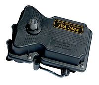
A valve actuator screws onto the top of a 2 way or 3 way valve and provides motorized control to move the valve from one position to another. The valve actuators are powered by 24V AC and plug into an automation panel.
The actuators can rotate the valve diverter up to 180 degrees. The actuator has adjustable limit switches to set the two stop positions.
The actuator has a toggle switch to manually rotate the valve and to synchronize the set positions with the automation panel.
The actuators operates all 2 way and 3 way Pentair, Jandy, Ortega, and Compool valves.
Manufacturers
- Jandy JVA 2444
- Pentair CVA24. Pentair has three model numbers for the CVA24. The only difference is their preset cam setting and the 90 degree and 120 degree actuators cost almost twice as much:
- 263043 90 degree actuator - $374.99
- 263044 120 degree actuator - $399.99
- 263045 180 degree actuator - $211.99
- Pentair IntelliValve
- Intermatic PE24VA
- Compool CVA-24 is now the Pentair CVA24
- Hayward/Goldline GVA-24 (Goldline Valve Actuator).
All of the above actuators work basically the same, are interchangeable, and work with all automation panels. If an automation panel supports one manufacture valve any of them should work.
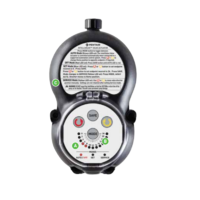
Pentair IntelliValve
The Pentair IntelliValve is a recent product that has the potential to have more than 2 stop points when Pentair add those features to it's automation panels.
Although there are 24 lights, there are actually 48 positions. The diverter within the valve housing moves 3.75 degrees for each push of the RED or YELLOW arrows. You can select any of these 48 positions as the home and second saved positions.
The IntelliValves 2 stop points can be set with the control panel on the valve. The programming of the HOME and second position fairly intuitive and straight forward once you do it once or twice. The instructions in the manual, not as much.[1]
Basically you just press the MODE button until the blue SET light illuminates. Move the RED arrow to the first position that you want to save and press SAVE. Then move the RED button to the next position that you want to save and press SAVE. Press the MODE button until the green AUTO light illuminates. The actuator will move the valve to the first saved position. If you want home to be the other saved position, then just press the RED and YELLOW buttons simultaneously while in the AUTO mode and the actuator will move the valve to that second position and consider it HOME. That's it basically.
SERVICE mode is used to change the valve position to any other position other than the two saved positions. More like a "manual" mode.
The IntelliValve has green and yellow communication wires that are not used now and are reserved for future use with future automation systems.[2] The extra green and yellow wires are for RS-485 signal that eventually the IntelliCenter will use to control the valve so that it can stop at multiple positions.
Jandy Smart JVA Assembly
The SMART JVA controls a standard Jandy JVA valve and adjusts the amount of water flow to a water feature from a AUX button.
The SmartJVA add-on board will allow Aqualink owners to be able to real-time set the amount their automated valves (JVAs) are open from 0-100% in 5% increments.[3][4]
There are still only 2 programmed stop points, "off" which is 0%, and on which is the percent you last saved. But in addition, you can real-time set the percent up or down in 5% increments from whatever controller you are using. With the smartphone it is true real-time and with the OneTouch and PDA you have to go to the SmartJVA setup to set.
The requirements to set up SmartJVA are a OneTouch controller or iAqualink with Rev T or newer.[5]
Jandy SmartJVA Module **HOW TO GET IT WORKING**
Jandy Valve Actuator Operation
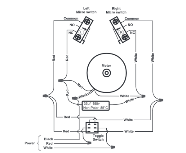
One leg of a 24 VAC transformer secondary supplies voltage to the common terminal of a SPDT (single-pole, double-throw) relay.[6]
The N.C. (normally closed) terminal of that relay is connected to the red wire of the JVA cord, and the N.O. (normally open) terminal is connected to the white wire of the JVA cord.
The completion of the circuit is through the black (common) wire of the JVA cord.
When the coil of the SPDT relay is de-energized, voltage is supplied from one leg of the transformer secondary to the common terminal of the relay and then down the red wire of the JVA cord to the toggle switch at the rear of the JVA.
The toggle switch then routes the voltage to either the lower microswitch (toggle in ON 1 position), the upper microswitch (toggle in ON 2 position), or to neither microswitch (toggle in OFF position).
If the voltage is routed to the lower microswitch, and that microswitch is closed, the voltage passes through the motor to the black wire and then back to the other leg of the transformer secondary to complete the circuit.
The motor will then rotate clockwise, turning the gear train (and ultimately the output shaft) until the lower cam comes in contact with the lower microswitch, which opens the circuit and stops the motor.
If the voltage is routed to the upper microswitch, the motor rotates in the opposite direction until the upper cam lobe comes into contact with the upper microswitch, which stops the rotation.
If the coil of the SPDT relay is energized, the voltage travels through the white wire to the toggle switch, which as above, routes it either to the lower microswitch for clockwise rotation or upper microswitch for counterclockwise rotation, with the voltage traveling back to the black wire to complete the circuit.
The capacitor, which is wired in parallel with the motor, keeps the motor rotating in the correct direction and ensures that the JVA rotates with the proper torque.
Repairs
Jandy Diverters Parts Breakdown
Leaks
There is a small shaft O ring and a larger cover O ring that can leak. Check the parts catalog for your valve to determine the O ring size for the diverter size you have.
Use Pool Lube when replacing O rings or when opening and closing valve assemblies.
Micro Switches
The actuators have two limit micro switches that turn off the motor when the reach a position. These switches often fail.
Sometimes removing the microswitches from the actuator in question and examining them, as well as the other parts of the actuator, can get it working. Short the leads to each switch and confirm that the motor operats in both directions. Test the continuity of each switch and find if they both worked reliably (at least on the kitchen counter). Then reassemble everything and the actuator may work fine.[7]
The switch is an Omron Basic/Snap Action Switches SS-5T that can be bought at Mouser.[8]
The Hayward GVA-24 actuator takes an Omron SS-5GL13T microswitch. The only difference between that and the SS-5T is the lever.[9]
It takes about 5 minutes per actuator to do the labor. You need two Phillips screwdrivers (one medium and one small) to do the work.[10]
Don't forget to cut off power to the actuators before you work on them. Putting the panel in SERVICE MODE still leaves 24V going to the actuator for the manual toggle switch to work. You need to disconnect the actuator plug at the panel or power down the panel.
Then install the switches in exactly the same orientation as the old ones. Try not to bend the connectors on the switches when you reinstall the wire clips.
Do NOT bend the Microswitch leads. You may cut off the center one if you like, but do not stress the other leads. Bending the lead stresses the internal connection of the leads and leads to pre-mature failure. Soldering ALL of the connections within the actuator will prevent other failures due to bad contact with the .110" slide on connectors to the micro-switches and the connections to the capacitor and motor leads.[11]
Toggle Switch
The toggle switch on the Jandy actuator is part of the PCB w/Toggle Switch Kit 2444 - R0441700.
Periodic Maintenance
Once the top is off, remove the screws holding the frame to the bottom plastic shell and inspect the gears. Water may get into and rust the gears, which will need replacement. Be sure they are well lubricated with thick grease.[12]
Lubricate the handle shaft that sticks up through the top plastic shell with thick grease to avoid water seeping down the shaft.
The long gasket that seals the top and bottom shell pieces should be inspected and lubricated. Replace if cracked or degraded.
Tips
Screws
To mount an actuator, you have to remove 4 screws and install 4 longer screws.
The problem with using a valve actuator from one brand and a valve from a different brand is that the screws have a different thread.
The screws are self tapping and they will bite into the existing plastic threads, but it will damage the threads.
By using the same brand, the thread is the same and you should be able to avoid cross-threading.
Long screws for mounting any actuator on Pentair valves are Pentair p/n CVA-SCRJ.[13]
Lubrication
- Apply silicon grease (plumber's grease) to the rubber gasket and a little to gears.[14]
Valve rotates to the wrong position
- Change the switch on the back or bottom of the actuator between ON1 and ON2.
Manual Override, Power On (Jandy and should work for others)
- Move the toggle switch located on the bottom of the actuator to the opposite position (ON 1 switch to ON 2 or vice versa). This will rotate the motor to the opposite position.[15]
- Return the toggle switch to the original position after use.
Manual Override, Power Off (Jandy and should work for others)
- Move toggle switch located on the bottom of actuator to the OFF (center) position.[16]
- Unscrew (counterclockwise) the locking knob above the handle four (4) full turns.
- Push down on the locking knob (not the handle). This will disengage the gear train and allow the handle, and thus the valve diverter, to be moved to any position.
- To return the actuator to automatic position, pull up on the handle while turning it clockwise or counterclockwise until you feel the shaft slide up into the gear train. Turn the locking knob down (clockwise) until snug.
- Put toggle switch back to the original position.
Actuator Stops in Wrong Position
Follow the instructions on page 7 section 4.2 in the Actuator Manual to reset the cams for your desired stop points
It takes some patience and trial and error to get them set.
Or get the Jandy SMART JVA if you have Jandy Aqualink RS automation and make your JVAs adjustable in 5% increments from your Aqualink controllers.
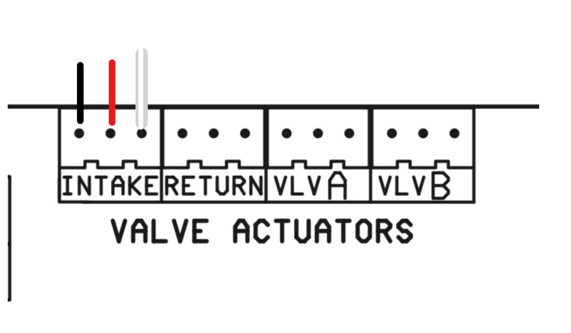
JVA 2444 Wiring
- Wire - 3-conductor[17]
- Black - Common
- Red - Switch Leg
- White - Switch Leg
JVA 2444 Power Requirements
- Each JVA requires .75 amps at 24V AC[18]
Connector
The connector used on actuators is the JST XH 2.54MM 3 Pin available on Amazon and electronic supply houses.
The punch-down JST connectors are colored differently (white/maroon/black) depending on the wire gauge they can accommodate, so be careful to get the black ones.[19]
A great thread showing the breakdown, testing, and repair of an old actuator. https://www.troublefreepool.com/threads/cva24-t-actuator-details.226632/page-3#post-1988733
.
- ↑ https://www.troublefreepool.com/threads/pentair-actuators-can-i-have-a-valve-half-opened-vs-all-the-way.237702/post-2080800
- ↑ https://www.troublefreepool.com/threads/pentair-intellivalve-green-and-yellow-wires.198551/post-1752587
- ↑ https://www.troublefreepool.com/threads/jandy-smartjva-module-how-to-get-it-working.178175/post-1581908
- ↑ https://www.troublefreepool.com/threads/jandy-smartjva-module-how-to-get-it-working.178175/post-1581928
- ↑ https://www.troublefreepool.com/threads/jandy-smartjva-module-how-to-get-it-working.178175/post-1581945
- ↑ https://www.troublefreepool.com/threads/cva24-t-actuator-details.226632/post-2131556
- ↑ https://www.troublefreepool.com/threads/spa-actuator-repair-microswitches.190671/post-1683262
- ↑ https://www.troublefreepool.com/threads/pentair-valve-actuator-fix-new-switches.99985/post-1227431
- ↑ https://www.troublefreepool.com/threads/what-did-you-do-to-your-pool-today.89968/post-2147933
- ↑ https://www.troublefreepool.com/threads/pentair-valve-actuator-fix-new-switches.99985/post-862665
- ↑ https://www.troublefreepool.com/threads/pentair-valve-actuator-fix-new-switches.99985/post-934524
- ↑ https://www.troublefreepool.com/threads/pentair-valve-actuator-fix-new-switches.99985/post-935201
- ↑ https://www.troublefreepool.com/threads/heres-part-long-screws-for-pentair-valve-3rd-party-actuator-mounting.278597/post-2441678
- ↑ https://www.troublefreepool.com/threads/pentair-valve-actuator-fix-new-switches.99985/post-935339
- ↑ https://www.jandy.com/-/media/zodiac/global/downloads/h/h0570800.pdf?force=1
- ↑ https://www.jandy.com/-/media/zodiac/global/downloads/h/h0570800.pdf?force=1
- ↑ https://www.jandy.com/-/media/zodiac/global/downloads/h/h0570800.pdf?force=1
- ↑ https://www.troublefreepool.com/threads/replacement-jva2440-actuator-cable-and-toggle-switch.130716/#lg=post-1155416&slide=0
- ↑ https://www.troublefreepool.com/threads/connector-for-valve-wiring-on-pentair-easy-touch-4-controller.268826/post-2355265


