Pentair MasterTemp Heaters
The Mastertemp heater is a re-packaged Sta-Rite Max-E-Therm heater. Sta-Rite introduced those heaters into the market prior to them being bought by Pentair. Then Pentair immediately put the heater into their "cube" design and began selling the heaters both ways. The Max-E-Therm is still in production under the Sta-Rite name.
Pentair has a regular residential mode MasterTemp heater and a commercial ASME certified performance model[1] MasterTemp heater.
The commercial ASME certified performance model features include:[2]
- New bronze header design for easy access to the thermal regulator and bypass valve service without use of special tools
- Upgrades to thermal regulator include a governing stainless steel sleeve for better wear protection
- All internal components of the bronze header are plastic for lightweight, corrosion and wear protection
- Ignition Control Module includes more diaphragm spring force for better gas control and robust operation.
- Fuller pre-mixed system with highly efficient air and gas mixture allows for faster heat up times
- Efficiencies up to 84%
Both the MasterTemp and MasterTemp ASME come in an HD model that has a cupro-nickel exchanger. Pentair claims the cupro-nickel exchanger stands up to the harshest of applications, like low pH, high flow or heavy use.[3]
The MasterTemp heater is a compact, lightweight, efficient, induced-draft, gas fired high performance pool and spa heater that can be directly connected to schedule 40 PVC pipe. The MasterTemp heater also comes equipped with the Pentair multifunction temperature controller which shows, at a glance, the proper functioning of the heater. All MasterTemp heaters are designed with a direct ignition device, HSI (hot-surface ignition), which eliminates the need for a standing pilot. The MasterTemp heater requires an external power source (120/240 VAC 60 Hz) to operate.[4]
Pentair HEATERS & HEAT PUMPS Catalog
Pentair HEATERS & HEAT PUMPS PARTS Product Catalog 2022
MasterTemp Connected Heater
A running change to all Pentair MasterTemp & StaRite Max E Therm heaters, took place on the afternoon of 5/7/2021.
All heaters made before 5/7/2021 have membrane keypads with five buttons, which identifies them as “Non Connected” models.
Connected Heater Features:
- RS485 connection to IntelliCenter Automation
- Upgraded menu structure: Flame strength indicator, Runtime, Cycle Count, Error Code Log
- Ability to control an external bypass valve
- Six button membrane keypad
There are significant parts changes with the "Connected Heater" that the Pentair MasterTemp & StaRite Max E Therm : Parts Matrix for “Connected Heater” Update May 2021 lists.
Different parts between heater versions include:
- PCBA
- Membrane Keypad
- Ignition Control Module - ICM -Fenwal box
- Wiring Harness
- Bypass Valve Kit
Check that you have the correct replacement part numbers for the heater version you have if you are replacing these parts.
Discussion about the use of RS-485 in the Connected Heater is being discussed in the New Model Pentair MasterTemp Heater thread.
How to Read a Serial Number to Determine MasterTemp Manufacturing Date
The first four digits indicate the product line (ignore those digits)
The next three digits of the serial number are the day of the year:
- January 1 would be 001.
- December 31 would be 365.
The next two digits are the year:
- 2018 would be 18.
- 2021 would be 21.
And then all the rest of the digits are random (ignore those digits.) Examples:
- 123412621XXXXXXXX
- the 126th day of 2021is May 6, 2021 (not a Connected Heater)
Example:
- 123412721XXXXXXXX
- the 127th day of 2021 is May 7, 2021 (this is a Connected Heater)
Mastertemp ASME Heater Model
The HD models MasterTemp contain cupro-nickel heat exchnagers.
The differences between the standard model and the HD model are the heat exchanger, manifold, and water pressure switch.
The standard model has a black manifold and the HD has a bronze manifold.
The HD ASME Water Pressure switch is a larger diameter and specific for the bronze header and criminally overpriced.[5]
MasterTemp Gas Heater versus UltraTemp Heat Pump
UltraTemp Heat Pumps and MasterTemp Gas Heaters are very different technologies.[6]
Heat pump technology is the most efficient way to heat a pool, however, the lower BTU rating of heat pumps means that it can take longer to heat the pool to a desired temperature. Heat pumps also have reduced heating performance when the ambient air temps are very low (when ambient temp drops below about 50F.) This is because heat pumps do not make heat; they simply capture the free heat from the air and move it into the water. Heat pumps are typically sized from 70,000 BTU to 140,000 BTU.
Gas heaters work well in all ambient air temps, and they have higher BTU output (commonly up to 400,000 BTU.) Gas heaters are great if you want to heat water up quickly in all weather conditions, but a gas heater is much less efficient than a heat pump.
The US Dept of Energy has some good, unbiased articles about choosing the right kind of pool heating equipment for your needs - Swimming Pool Heating
Here’s a blog article from pool equipment retailer In The Swim that sums it up fairly well, especially the comparison table and the two lists of “best choice” points, located about halfway down the page - Pool Heaters: Heat Pumps vs. Gas Pool Heaters | InTheSwim Pool Blog
Heater Description
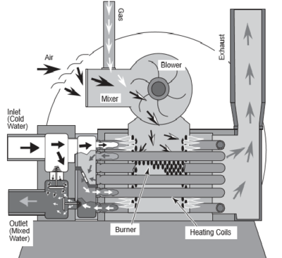
Precisely matched orifice plates meter the air and gas into the mixer. The blower draws the air and gas through the mixer and forces it into the burner’s flame holder. A sealed heat exchanger surrounds the flame holder, discharging exhaust gases out the flue.
Two inch PVC water piping connects directly to the manifold/header on the heat exchanger using 2" PVC slip unions provided with the heater. The outer manifold remains cool; no heat sinks are required. A thermal regulator and an internal bypass regulate the water flow through the heat exchanger to maintain the correct outlet temperature. The heater operator control panel board assembly is located on top of the heater.
Sequence of Operation
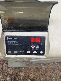
Normal boot up is 888, 128 and then rX where X is the software revision number.
Normal boot up for the Connected Heater board with the six button control panel may just display RX where X is the software revision number.
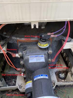
An electronic temperature sensing thermistor in the manifold adapter inlet controls the heater operation. When the inlet water temperature drops below the temperature set on the operating control, the burner controller supplies power to the combustion air blower through a series of safety interlocks. The interlocks consist of:
- the pressure switch (PS), which senses that the pump is running,
- the high limit switch (HLS), which opens if the heat exchanger outlet temperature goes above 135° F (57° C), and
- the air flow switch (AFS), which senses the pressure drop across the air metering orifice,
- the automatic gas shut-off (AGS) switch, which opens if the heat exchanger outlet temperature goes above 140° F (60° C).
- the stack flue sensor (SFS), which shuts down the heater if the flue gas temperature reaches 480° F (249° C).
The air flow switch (AFS) senses the pressure drop across the air metering orifice. As soon as there is sufficient air flow, the AFS closes, closing the circuit to the hot surface igniter (HSI), which ignites the fuel mixture. On a call for heat, the blower and HSI are energized. In about 20 seconds, the gas valve opens and ignition occurs. The HSI then switches to a sensing mode and monitors the flame.
The heater is equipped with a digital operating control that enables the user to pre-set the desired pool and spa water temperatures. The control enables the user to select between pool and spa heating, and features a digital display that indicates the water temperature.
The Jandy JXi is the same type of design.
The blower pushes the air gas mixture into the flame holder inside the combustion chamber.
Installation
Heater Bypass
Automatic Heater Bypass
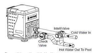
The MasterTemp Connected Heaters support an automatic heater bypass using an IntelliVlave connected to the socket labelled BP_VLV on the PCBA in the heater. Pentair has the AUTOMATIC BY-PASS VALVE KIT (P/N 462048) FOR MASTERTEMP® AND MAX-E-THERM® POOL AND SPA HEATERS
Pentair says "in conjunction with a Pentair IntelliFlo VF pump the automatic by-pass valve functionality of the latest MasterTemp heater will improve the head loss through the pool system, reduction of pump power consumption and the longevity of the heater by automatically taking the heater mostly out of the flow loop when not in use."
By-pass Valve Description - The purpose of the automatic BPVALVE (bypass valve) feature is to by-pass the flow of water from the heater inlet to the heater outlet when the heater is not firing. There is a minimal amount of water flow through the heater when the heater is not firing, and a maximum water flow through the heater when the heater is firing.
By-Pass Enabled - When the BYPASS VALVE feature is enabled and there is a call for heat, the by-pass valve closes to allow water to flow through the heater. It takes 30 seconds for the bypass valve to rotate to the closed position. This allows the valve to complete rotation so there is sufficient water flow and pressure to prevent the water pressure switch from trigging an error. When the call for heat ends, the water flow continues through the heat exchanger for a cool down period of one minute. After the cool down period, the by-pass valve will rotate so that water no longer flows through the heater.
By-Pass Disabled - When the BYPASS VALVE feature is disabled, there is no automatic switching of the by-pass valve when the heater starts a heating cycle. The valve stays in the position and water always flows through the heater.
Manual Heater Bypass
A manual heater bypass allows the heater to be taken out of the water loop for maintenance or if there are concerns about the water quality such as low pH that can damage the heat exchanger.
Pentair recommends a manual bypass when the water flow rate exceeds the maximum 120 GPM. After installing the valve, adjust the valve to bring the flow rate within the acceptable range. Then remove the valve handle or lock it in place to avoid tampering. See page 13 of the Installation Manual
Heater Cooldown
The filter pump should run continuously when the heater is on, and for at least 5 minutes after the heater turns off. Any switches in the pump circuit (including circuit breakers) that can disconnect the pump must also disconnect the heater. See page 29 of the Installation Manual
A time clock controlling the filter pump should have a low-voltage Fireman’s Switch that switches off the heater at least 15 minutes before shutting off the pump.
Firemans Switch
The "Fireman's Switch" is a poor name for the 2 wire 24 volt AC remote control system of the heater. The Fireman's Switch is a 2 wire control that can connect to automation such as the EasyTouch or IntelliCenter or to a timer. The current is less than 500 milliamps (0.5 amps).
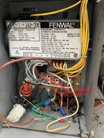
The firemans switch is the two center bottom terminals with the yellow wires on the block below the Fenwal box. The right terminal has the fuse. You remove the jumper and run a wire from one fireman's switch terminal to the one connection of the J19 terminal in Easytouch and then a wire from the other J19 terminal back to the other fireman's switch terminal or similar connections in other automation controllers.
- IntelliCenter: Insert the conductors into the GAS HEATER two-screw terminals (J2) on the upper right of the mother board.
- EasyTouch Control System: Insert the conductors into the GAS HEATER two-screw terminals (J19) on the motherboard.
- IntelliTouch Control Personality circuit board: Insert the two conductors into the GAS HEATER (J30) two-screw terminal on the left side of the Personality circuit board.
The blower will continue to run for about 45 seconds after the burner shuts off.[7]
RS-485 Remote Control
A running change to all Pentair MasterTemp & StaRite Max E Therm heaters, took place on the afternoon of 5/7/2021. The new version heaters are called Connected Heaters and have the RS-485 comm port and a "6-button" membrane keypad (with a MENU button).[8]
While the manual says the MasterTemp can connect to Pentair control systems via a 3 wire RS-485 connection the connector is not on older boards. See pages 37-40 of the Installation Manual
IntelliCenter and RS-485 Heater Control
When using the RS485 comms, adjusting the set point adjusts the IntelliCenter and the MasterTemp heater set points simultaneously. No more needing to verify the heater set point has not been altered and is above the IntelliCenter set point.[9]
This is different then when using the 2 wire fireman's switch, the set point adjustment only changes the Intellicenter set point, it has no effect on the actual set point of the heater. Meaning if for some reason the heater setpoint changes from 104, then you have to manually adjust it back at the heater.
MasterTemp RS-485 Combo Conversion/Replacement Kit
CONNECTION DIAGRAM - RS-485 COMBO CONVERSION REPLACEMENT INSTRUCTIONS (USA)
This kit is an unreleased bundle that includes all 4 parts that would be required to convert an older MasterTemp to have the newer RS-485 features that Pentair introduced as a running change this year.
The kit that will be released in a single bundle sometime in the future contains the following items. All of these items can be purchased separately now.
- Wiring Harness
- Ignition Control Module
- Control Board
- Membrane Keypad
Pentair does currently sell each of the four parts individually (a la carte), but the bundle kit is not released yet.
Although converting an older MasterTemp to RS-485 is technically possible, it is highly discouraged and here is why. One of the required steps would be to replace the whole wiring harness inside the heater, which would take a really long time as it requires removing and replacing every single wire connection at every terminal, every sensor, every connection point to include the ignition control module, control board and the membrane keypad. Pentair says that it would take even a seasoned pool professional a long time to complete the job…
Pentair said that in the future, they plan to release a kit that includes all four of those parts in a single bundle. At that point, a person could upgrade an older heater by buying the kit/bundle of four parts (they would order one part number and receive one box that contains all four parts.)[10]
Theoretically, you could today order part #1 & #2 & #3 & #4 individually (you would order four separate part numbers and get four separate boxes) and accomplish the same thing, but Pentair expects very few people to go through the trouble of taking apart an older heater to install all four parts just for the sake of doing an elective upgrade, which is why the four part kit/bundle remains unreleased.
Changing the display between Centigrade (°C) and Fahrenheit (°F)
To toggle the display between degrees Centigrade (°C) and degrees Fahrenheit (°F):
- Turn the Operating Control OFF.
- Press ^TEMP or down TEMP for 5 seconds. The display will flash once and change modes (°C to °F or vice versa).
- Turn the Operating Control ON.
When either the ^TEMP or down TEMP buttons are depressed, the digital display will indicate the temperature setting.
After five seconds, the display will return to the actual pool/spa temperature.
Maximum Temperature Set Point
This applies to the older 5 button model. The 6 button connected model allows a full temperature range from 65F to 104F at installation.
The heater comes factory set with a maximum temperature set point at 78° F (25.6 c). for the pool mode and 100° F (37.8 C). The Installation Manual describes how to increase the maximum temperature set point of the pool and spa. It involves unbolting and removing the door panels, accessing the control panel board on the underside of the top cover, and locating the yellow button on the corner of the control board.
Altitude Adjustments
Air is thinner and less dense as the altitude increases. A natural gas or propane heater needs an optimum mixture of air and gas. If the air/gas mixture is incorrect you will have an orange yellow flame instead of a good blue flame.
At higher altitudes the gas needs to be adjusted for the proper air/gas mixture.[11] The Pentair Mastertemp is good to 9,000 feet.
Below or Above Pool Installation
The MasterTemp Installation Manual says the following:
The water pressure switch is set in the factory at 3.00 PSI (± 0.75 PSI). This setting is for a heater installed at pool level. If the heater is to be installed more than 1’ above or below, the water pressure switch must be adjusted by a qualified service technician. See page 44, Figure 38
FLOW SWITCH: If the heater is installed more than 5’ above the pool or more than 4’ below the pool level, you will be beyond the limits of the pressure switch and a flow switch must be installed.
Locate and install the flow switch externally on the outlet piping from the heater, as close as possible to the heater. Connect the flow switch wires in place of the water pressure switch wires.
What Do the Diagnostic LEDs Mean on the Pentair MasterTemp?
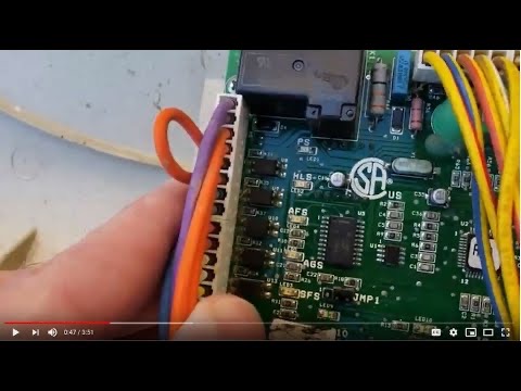
Diagnostic LEDs are on the back of the older 5 button non-connected Pentair MasterTemp heater board.[12] The 6 button RS-485 Connected Heater displays the diagnostics on the heater display or IntelliCenter display.
The following are the LEDs:
- .....PS (Pressure Switch)
- .....HLS (High Limit Switch)
- .....SFS (Stack Flue Sensor)
- .....AFS (Air Flow Switch)
- .....AGS (Automatic Gas Shutoff).
- .....Service System
- .....Thermistor
- .....Heating
- .....Pool On
- ...Spa On
- ...Service Heater.
HLS (High Limit Switch) Error
The HLS is often caused by lack of sufficient water flow through the heat exchanger. This can be due to several things:
- Thermal regulator not opening.
- External bypass open.
- Internal bypass broken.
- Pump too small or on too low rpm.
- Clogged filter.
- Scale in heat exchanger.
Start by checking the thermal regulator.
E05/E06/SFS (Stack Flue Sensor) Error
November 2022 - there are increasing reports of stack flue sensors failing on MasterTemp heaters 1 to 10 years old.[13]
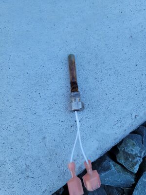
The part number for the Stack Flue Sensor is Pentair 42002-0024S. The generic ones found on Amazon for about $15.00 seem to work as well as the Pentair $150 sensor.
Pentair tech support suggests testing their new ones before installation.[14] The sensor may be tested with an ohm meter (3.8 MegOhms @ 77F) If you decide to get a new SFS, check the stack flue temp when you get it back together and running to confirm that the stack flue temps are where they should be, and not too high.
E05 errors are due to things like a sooted exchanger(fuel delivery, venting), scaled up exchanger (water side), or a low water flow.[15]
E05 and E06 are more or less the same thing - Problem with the Stack Flue Sensor.[16]
You can get an E05(open sensor) if a rat chews through the wire(s). An E06 is a shorted sensor, or if the board thinks it is a switch, and not a thermistor (didn't get programmed when it was installed).
The Stack Flue Sensor prevents the flue gas output from exceeding 500°F ±18°F (260°C ±8°C).
If you hold down POOL or SPA button for at least 10 seconds it displays the exhaust temp. Normal temps should be ~290-350.
Turn the heater on. The fan will come on for about 30 seconds, then you will hear a click, and the heater should fire. At that moment, which ever thermostat you are using (POOL or SPA) hold that button down for ~10 seconds. Display should change from water temp to exhaust temp. Normal temps should be in the range of 290-350. 350-500 is considered high and you should look for:[17]
- Sooted exchanger(external) due to improper gas pressure or lack of proper venting. either supply of fresh air or exhaust, or both. Heater is being starved of air and the resulting air/fuel mix is too rich (fat).
- Calcified exchanger (internal) due to improper water chemistry. Note: Not necessarily right now, but at some point in the past, and for a while. This does not happen overnight.
- Flow or velocity issue. Water is moving too slowly through the exchanger, gathering or absorbing too much heat, and is not carrying it away quickly enough to keep the heater at a workable temp. In this case, you may have a valve closed down, but not fully closed, or may be wanting to save a little more money on your electricity bill, so you turned down your VS pump as low as you can get away with. You will need to turn it back up to correct this !
Check the interior for obstructed venting (intake and exhaust). Animal nests, spiders, mud dauber nests against the air blower vent, can all block the air flow and lead to an overheat and SFS error.
You see those problems a lot more then a sensor that has gone bad. Although continued high temps could eventually cause a SFS to fail. The SFS will let the heater stack temp to run up to 480 degrees before it will shut the heater down. In the case of a sooted exchanger, the stack flue temp would rise slowly over time (weeks/ months) subjecting the sensor to extended over temp conditions.
The Indoor Stack Flue Switch (ES2) / Stack Flue Sensor (SFS) is located on the Exhaust Elbow.[18]
WARNING - Risk of carbon monoxide poisoning. BE SURE to seal the Stack Flue Sensor with a bead of RTV sealant before threading it into the exhaust elbow.
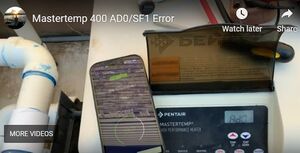
AD0 and SF1 show up when the "Off" button is held down to program the stack flue sensor.
If these show up without pressing the OFF button, it's probably a bad membrane pad with a stuck "Off" button.
SF1 is not an error code; it is a program setting.
_____________________________________________________________
1. Turn the power to the heater ON.
2. Press and hold the OFF button on the membrane pad until the 3-digit display shows “Ad0” or “Ad1” (about 10 seconds).
3. Release the button and then press it momentarily.
The 3-digit display will now show either “SF0” or “SF1”.
Board must be set to “SF1” for the heater to operate with a Stack Flue Sensor installed.
4. If the display reads “SF1”, it is correctly set.
If it reads “SF0”, use the arrow buttons on the membrane pad to set it to read “SF1”.
5. Momentarily press the “OFF” button to exit the program.
E05 Error with SFS Reading 40
If the SFS reads 80, then flashes to 40, then back to 80, then the 80/40 reading and E05 indicate that the board is not getting a reading from the sensor.
Try reseating the connectors on the SFS.
Otherwise it's a bad sensor or damaged wires.
If the sensor and wiring are good, the board is probably bad.
Disconnect the sensor and check continuity across its terminals.
Resistance should be 3.5-4.0 megaohms.
AGS Error
AGS errors are usually caused by a bad internal bypass. Too much water is bypassing the heat exchanger internally. What water that is going through is coming out too hot and tripping the AGS switch in the manifold.[19]
- Remove the leads from the AGS sensor and connect them together. Temp only for the test.
- Then, check the continuity of the sensor. It should be closed.
- Start the heater. If the sensor opens, immediately turn off the heater.
- If the sensor opens, it might be a bad sensor or the water is overheating.
- To test the sensor, put it in hot water to see where it actually opens.
- If the sensor does not open and the heater shuts off with an AGS light, the board is bad.
Refer to to pages 31 and 32 of the Installation Manual[20] the connection and ladder diagrams. You will notice that all of the safeties and gas valve are run through the operating control and ignition module.
You should first have 24 volts ungrounded to IND on the ignition module through water pressure switch and hi limit to start the inducer (blower) motor which will then make the air flow switch to put 24 volts ungrounded to the TH (W on some) terminal on the ignition module. This should start the ignition trial.[21]
After the igniter warm up time the ignition module powers the gas valve through VAL on the ignition module, but this also goes through the operating control VAL which then goes through the AGS safety to the gas valve. This is your ignition module Fenwal 35-662944-013 and it is user specifically modified which is why you don't see a W terminal.
You should notice on the ladder diagram that one leg of the 24 volt side is grounded. Right after the heater fires up, if you add a jumper from the ignition module VAL terminal to the TH terminal on the gas valve and the heater keeps firing then the problem is either with the AGS switch or the operating control. If it still shuts down then the problem is with flame sensing.
AFS Error
AFS is the air flow switch that senses if the blower is on and there is sufficient air flow to the burner. Sequence is blower motor should turn on, AFS senses air flow through a white tube down by the burner can, and switch closes to start the ignition sequence.
You can gently blow into the white tube and you should hear the click of the air flow switch turning on. Check the white tube for cracks or breaks. The white tube is not available as a separate part and comes with the Pentair MasterTemp & Sta-Rite Max-E-Therm Air Flow Switch assembly P/N 42001-0061S.
If you hear the air flow switch closing then check the continuity of the air flow switch relay using a multimeter. Connect the multimeter to the two contacts on the air flow switch after removing the heater wires. You should see it electrically open when no air is blown into the switch and closed when air pressure is through the tube.
Testing the Air Blower
Check that the blower motor rotates freely before doing electrical checks. Sometimes the blower has began running by simply cleaning debris from the fan area or removing the cover to the blower motor and using a screwdriver to manually turn it.
Note: No guarantees on anything. Only do what you know that you can do safely. Do at your own risk.
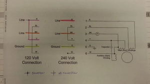
The blower has 3 sets of windings.[22] 2 main run windings and an auxiliary start winding. Red and blue go to one set of windings. Black and yellow go to the other set.
- For 120 volts, the windings are in parallel.
- For 240 volts, the windings are in series.
The auxiliary start winding is in parallel with the black --> yellow winding.
Remove the capacitor and test for resistance from red to blue and black to yellow. The values should be the same.
- Label the capacitor wires C1 and C2.
- Test from C1 to C2, C1 to black, C1 to yellow and C1 to white.
- Test from C2 to black, C2 to yellow and C2 to white.
Test from each wire to the green ground wire to see if any wires are shorted to ground.
Check the power going to the blower[23]:
- When the heater tries to start, you should be seeing 240 volts from red to black on the wires going to the blower.
- You can disconnect the blower plug and test the power at the red and black wires.
- Have the meter connected because the power might shut off after a few seconds.
- The red should be powered any time the heater is powered.
- So, you should get 120 volts on that leg before the heater tries to start.
- The black wire doesn't get power until the blower is supposed to be on. When the heater tries to start, power is applied to black and you should get 240 from red to black.
To test the motor directly wire as follows:
- For 240 volts, Black to hot leg, Red to the other hot leg, blue and yellow connected together.
- For 120 volts, red and yellow to one line, black to the other line and blue and white connected together.
- The white wire is connected to the black wire, so cap it off when applying power to the black wire so that it doesn't make contact with anything.
If the power test shows that the motor is good, the problem is likely to be with the ignition control module or the main board.
Note: the above is believed to be correct. It's presented as is. If you want to test like this, you do it at your own risk.
Do the resistance test first as that should tell you something.
Test the capacitance of the capacitor to make sure that it's correct.
One power leg is always connected to the blower motor and the black wire from F2 is the switched leg.
Exhaust Gas Temperature
While running, press and hold the On button to display the exhaust temperature (Older Models).
The new models use the Menu to get the SFS.
Here is what the normal exhaust temperature should be:
- Below 250 degrees...very low
- 250 to 290 ..................low
- 290 to 350.................acceptable
- 350 to 480 ..................high
- Above 480...................error/shutdown.
Note: HD models can be up to 75 degrees higher. HD models use a cupro nickel exchanger and the efficiency is slightly lower resulting in less heat transfer and more waste heat.
If the exhaust gas temperature is higher then normal then water may be bypassing the heat exchanger through a broken bypass valve.
If you hold down the "pool on" button, it stays on 80, then flashes to 40, then back to 80, then the 80/40 reading and E05 indicate that the board is not getting a reading from the sensor. It's usually a bad sensor or damaged wires.
Repairs
Parts diagrams including replacement part numbers are at HEATERS & HEAT PUMPS PARTS Product Catalog 2021
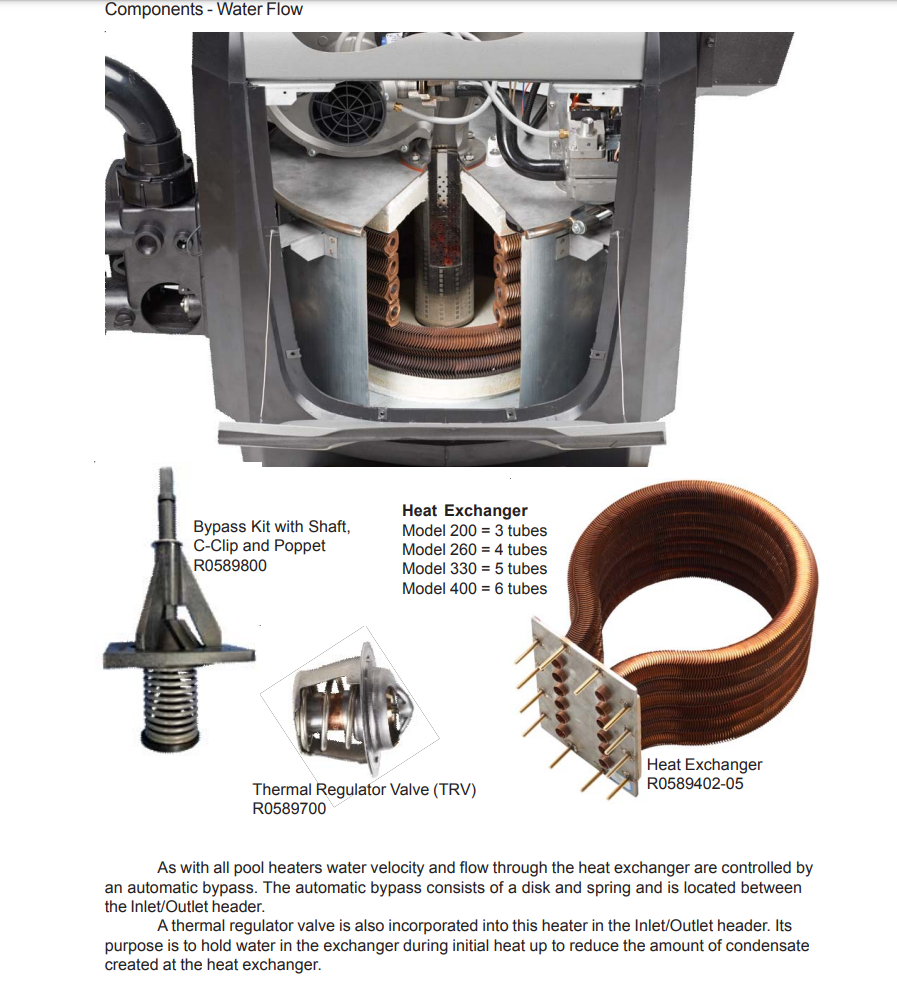
Thermal Regulator
The thermal regulator is behind a screw off cap between the in/out pipes in the heaters header. With the pump off, unscrew the cap and pull the regulator out. Note, if the regulator does not come out easily and feels like it hung up on something, then the bypass is broken and hanging in the way. If it comes out with no issues I'm sure you find it's all gunked up. Then use you fingers and stick them in the opening and feel up around towards the top middle and you should feel a round button like item, that's the bypass. If you feel it and it seems to be solid, then you are good with that.[24]
To test the thermal regulator Put it in hot water (130 to 140 F) to see if it opens.
The thermal regulator is sensitive to water chemistry and can get erosion.
Bypass Valve
If the bypass valve is broken the heater will short cycle and make noise. If you look in the hole where the thermal regulator goes, you should be able to see the black disk. If you look in the water inlet, you should be able to see the spring.
You will have to take the manifold off to replace the Internal by-pass kit P/N 77707-0001.
Guide to replacing the bypass valve is for the residential MasterTemp model.
The ASME commercial MasterTemp model has a different manifold with a 2-inch Pipe Plug, (for access to Internal BypassValve), located at the top of the Manifold.[25]
Bad Temperature Sensor
- The "E01" code is an indication of an open water temperature sensor that is also called the thermistor on the parts diagram.
- Problem - Heat will not fire, blower does not even turn... heat is set at 89*. membrane is showing water temp 107... easy touch panel temp reading is accurate (thermometer in pool 83*).[26]
- Thermistor p/n 42001-0053S Part 7 on page 54 of the MasterTemp Installation manual[27].
Blower not Operating
Listen closely when you turn the heater on, after it cycles through the 888, 128, R13. You may need to put your ear right next to the top of the heater (where the board is) to hear if the small relay on the board clicks (May sound more like a "tick" than a "click"), giving voltage to the blower. This click will be more subtle than the click you normally hear when the gas valve opens (you wont hear that one though if the blower never starts).[28]
If you can hear the click, look at the blower. No click, look at the board. If you are getting the AFS error, that means the safety switches have been satisfied, and the board should be telling the blower to start (power to relay coil).
Bad Igniter
If the blower starts, the attempt to light the flame starts, you smell gas, here the click, then it sounds like something closes. Repeats a couple times and throws the 3 blinks of the led on Fenwal box then you may have a bad igniter.
With a bad igniter you do not hear the woosh of the flame lighting and feel a burst of hot exhaust before it shuts down.
You can do some diagnostics on it and see if it is heating, examine it visually, check the resistance of it which should be 50 ohms, and check there is 120V AC going to the igniter when the heater starts.
A new igniter resistance is 50 ohms.
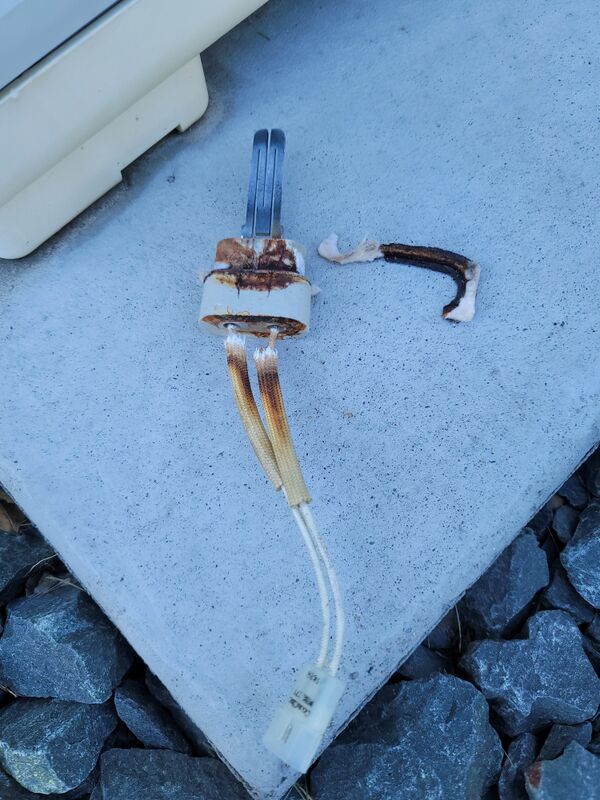
Below is an igniter that was removed from a MasterTemp heater where the flame would light but then shutdown due to a flame sense error.
It is interesting to note that the igniter corrosion also occasionally caused the GFCI CB to trip when the heater lit.
Flame Rectification Failure
After the gas valve opens, the HSI (Hot Surface Ignitor) will switch to a sensing mode to monitor the flame.
When the HSI switches to flame sensing mode, it is looking for a microamp current in the 1 to 10 microamp range (1.0 to 10 µA).
If the flame sensor does not read at least 1.0 microamps, the Fenwal controller will shut down power to the gas valve.
Does the heater briefly ignite and you get a puff of heat and then shuts down? If so you may have have a flame sensing problem. Heater Flame Sensing describes what may be happening and ways to fix it.
24V AC Fuse Blows
You can try removing the operating control board connectors at J1, J2 and J3 leaving only the 24V input to the control board and the firemans switch return to the control board at J7. Does the fuse blow? If so you have isolated the problem to the firemans switch and its wiring or the control board. If it doesn't blow, attach the connector at J1 and repower the heater. Does the fuse blow? If so, you have isolated the problem to the ICM or its associated wiring. The only connection at the ICM that should have zero or near zero ohms to ground should be the one lableled GND.
If the fuse blows with only the J7 connector in place, you can remove the J7 connector and check for continuity to ground on the 2 connections associated with the firemans switch. If they read as open, you have a problem with the control board.
The fuse for the Fireman’s Switch is a 1.25 Amp 1¼ x ¼” fast blow fuse, which is commonly available.
Replacing Wiring
Wiring can get chewed up by critters.
If any of the original wiring supplied with this heater must be replaced, installer must supply (No. 18 AWG, 600V, 105° C. U.L. approved AWM low energy stranded) copper wire or it’s equivalent.
Line voltage field wiring should be 14 gauge, with a circuit capacity of 15 Amps.
A complete replacement wiring harness for the old non-connected heater was p/n 42001-0104S. That is being replaced by the replacement wiring harness for the Connected Heater p/n 461107. The new New Wiring Harness for the Connected Heater comes with adapters to make it backward compatible with the non-connected heater.
Replacing Transformer
Pentair MasterTemp transformer P/N is 42007-0107. P/N 42007-0107s is for units made after 2003.
A bad transformer can cause the fuse to blow.
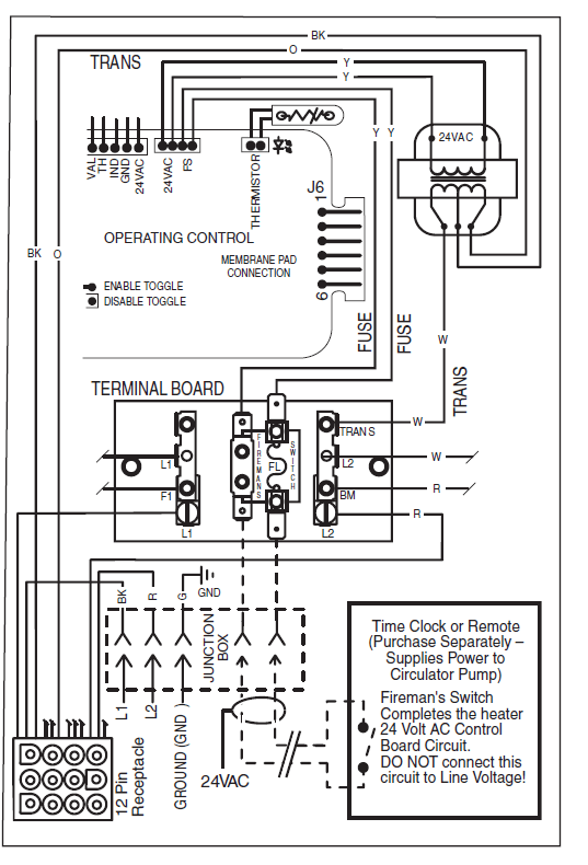
If the MasterTemp heater display does not light up when heat is commanded then check the power beginning at the Circuit Breaker. Use a multimeter and starting with the CB powering the heater check for voltage coming into the heater 12 pin receptacle. Confirm the correct voltage receptacle is installed and secure.
You can see on the diagram below the high voltage goes directly to the transformer that lowers it to 24V AC, Check for the 24V AC at the transformer and at the 24V AC plug into the main board.
If you have 24V AC to the PCB then the heater display should light up.
Main Board
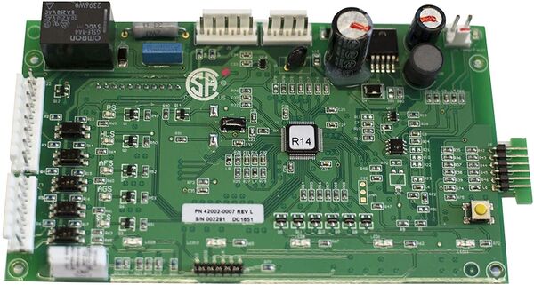
Control Board Kit (NA, LP Series) part number is 42002-0007S.
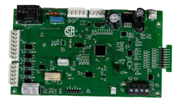
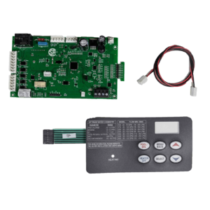
The old control board is being replaced by the new Connected Heater control board p/n 461105. The new Control Board Kit 461105 comes with "6 button" membrane keypad. When replacing a control board on an older heater that has a 5 button keypad, you will also need to update the heater to have the 6 button keypad.
See the Pentair MasterTemp & StaRite Max E Therm : Parts Matrix for “Connected Heater” Update May 2021.
The new control board comes in a kit with the required six button keypad and a red/black "flame" cable.
The included instructions show where to connect the flame cable between the board and the Ignition Control Module (ICM/Fenwal).[29]
Pentair Membrane Key Pad Replacement
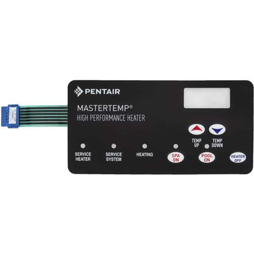
The membrane keypad sometimes fails and is separately replaceable with Pentair part number 472610Z for the five button keypad used on the non-connected heater version.
The Connected Heater version uses a six button keypad with a MENU button.
When replacing a control board on an older heater that has a 5 button keypad, you will also need to update the heater to have the 6 button keypad.
Stack Flue Sensor Control Board Setup
The Control Board is designed to work with both the Stack Flue Switch (on older heaters) and the Stack Flue Sensor (newer heaters). Please see Figure 2 to identify which type of Stack Flue protection you are replacing.
If you are replacing a failed Stack Flue Sensor, your Control Board should be set correctly for the new one. However, if you are replacing either an Outdoor Stack Flue Switch or an Indoor Stack Flue Switch, the Control Board will need to be reset as follows:
- Turn the power to the heater ON.
- Press and hold the OFF button on the membrane pad until the 3-digit display shows “Ad0” or “Ad1” (about 10 seconds).
- Release the button and then press it momentarily. The 3-digit display will now show either “SF0” or “SF1”.
- If the display reads “SF1”, it is correctly set. Go to Step 5. If it reads “SF0”, use the arrow buttons on the membrane pad to set it to read “SF1”.
- Momentarily press the “OFF” button to exit the program.
If at startup the heater is displaying Ad0 and SF1 then the OFF button is stuck. Replace the keypad.[30]
Ignition Control Module - ICM - Fenwal
The Ignition control Module (ICM) is manufactured by FENWAL.
The non-connected MasterTemp heaters use ICM p/n 42001-0052S. That is being replaced by a new ICM used in the Connected Heaters p/n 476223. The new Ignition Control module comes with adapters to make it backward compatible (works in old & new heaters).
Winterizing
Removing Water Pressure Switch
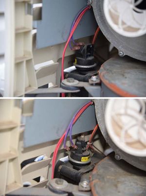
One of the winterizing steps in the manual is to remove the water pressure switch.[31]
Gain access to the heater by removing the two panels and locate the water pressure switch. Disconnect the two electrical leads and rotate the switch counterclockwise.
You may find the switch terminals hit the frame hits is the main body panel of the heater. You have to remove the side panel as well. The panel does come off.
Air Intake
Seal up the air intake with some plastic while in there.
Rat Proofing the Heater
Rats climb in through the air vents and nest in the heaters over the winter. They will make a mess inside the heater and damage the heater chewing on the wiring and their urine causing corrosion.
Rats and mice often make their home in the electrical box and chew up the wiring. You can repair the wire harness from any chewed damage.
You should check the blower rotates freely and may need to take the blower motor off and clean that out probably.
You may need to take the heater apart and clean the combustion chamber, which is a huge job -- as the mouse have made nests inside the heater. This messes up the ignition and the air flow.
MK Rat Proofing sells wire mesh kits to cover the vents or you can fabricate your own using 1/4" mesh wire screen or simple chicken wire and some sheet metal.
Some people put mothballs inside the unit to keep mice out.
Tips
- After start-up, the outlet water pipe should feel slightly warmer than the inlet pipe. If it feels hot, or if you hear the water in the heater boiling, there may not be enough water flow to the appliance. Make sure that the filter is not plugged. If water temperature remains high but the unit continues to operate, turn off the appliance and call your service technician.
- Operating this heater continuously at water temperatures below 68° F. (20° C) will cause harmful condensation and will damage the heater and void the warranty.
- When starting the heater for the swimming season with a water temperature below 50° F (10° C), the heater may be used to heat the water; however, make sure that the heater operates continuously until the water temperature reaches the heater’s minimum setting of 68° F (20° C).
- During cold weather, if there is no danger of freezing, operate the filter pump continuously even if the heater is not operating. If air temperatures are expected to drop below freezing (32° F/0° C), shut down the heater and winterize it.
.
- ↑ https://www.pentair.com/content/dam/extranet/aquatics/commercial-pool/literature-and-brochures/brochures/heaters/mastertemp-maxetherm-commercial-heater-brochure-english.pdf
- ↑ https://www.pentair.com/en/products/commercial-pool-spa-equipment/pool-heaters/mastertemp--high-performance-asme--certified-heaters.html
- ↑ https://www.pentair.com/en/products/pool-spa-equipment/pool-heaters/mastertemp_heater/sku/460805.html
- ↑ https://www.pentair.com/content/dam/extranet/product-related/product-manuals/pool-and-spa-equipment/mastertemp/MasterTemp_Pool_and_Spa_Heater_Installation_and_Users_Guide_English.pdf
- ↑ https://www.troublefreepool.com/threads/pentair-mastertemp-250-heat-exchanger-corroded-after-7-mi-seasons-advice-on-options.253169/post-2231797
- ↑ https://www.troublefreepool.com/threads/intellicenter-and-mastertemp-400-communication.209684/post-2073090
- ↑ https://www.troublefreepool.com/threads/heater-integration-with-easytouch-and-new-pump.202123/post-1784068
- ↑ https://www.troublefreepool.com/threads/intellicenter-and-mastertemp-400-communication.209684/post-2073090
- ↑ https://www.troublefreepool.com/threads/mastertemp-and-intellicenter.255624/post-2235417
- ↑ https://www.troublefreepool.com/threads/intellicenter-and-mastertemp-400-communication.209684/post-2074386
- ↑ https://www.troublefreepool.com/threads/gas-pool-heater-and-elevation-altitude.39163/post-327562
- ↑ https://www.troublefreepool.com/threads/mastertemp-400-shutdown-issue-e05-error.193404/post-1704484
- ↑ https://www.troublefreepool.com/threads/mastertemp-400-e05-error.266220/post-2329477
- ↑ https://www.troublefreepool.com/threads/mastertemp-400-e05-error.266220/post-2329488
- ↑ https://www.troublefreepool.com/threads/pentair-mastertemp-400-error-code-e05.73905/post-1191649
- ↑ https://www.troublefreepool.com/threads/mastertemp-400-e05-error.171793/post-1517990
- ↑ https://www.troublefreepool.com/threads/mastertemp-400-e05-error.171793/post-1514855
- ↑ https://www.pentair.com/content/dam/extranet/nam/industrial-flow-technologies/flow/ift-asset-library/pool-spa/S381(11-16-04).pdf
- ↑ https://www.troublefreepool.com/threads/mastertemp-400-wrong-temperature-readings.249820/post-2192096
- ↑ http://www.pentairpoolme.com/uploads/document/file/554/Manual_MasterTemp.pdf
- ↑ https://www.troublefreepool.com/threads/another-mastertemp-400-with-ags-led-service-heater-led.196702/post-1734928
- ↑ https://www.troublefreepool.com/threads/mastertemp-400-humming-already-replaced-the-run-cap-still-humming.199621/post-1762831
- ↑ https://www.troublefreepool.com/threads/mastertemp-400-humming-already-replaced-the-run-cap-still-humming.199621/post-1765494
- ↑ https://www.troublefreepool.com/threads/pentair-master-temp-400-problems.113128/post-1001404
- ↑ https://www.pentair.com/content/dam/extranet/product-related/product-manuals/pool-and-spa-equipment/mastertemp/MasterTemp_and_Max-E-Therm_Bypass_Access_Plug_Kit_Instructions_ASME_Models_Only_English.pdf
- ↑ https://www.troublefreepool.com/threads/mastertemp-400-ng-bad-board.192416/
- ↑ https://www.pentair.com/content/dam/extranet/pentair-pool/commercial/manuals/heaters/Manual-MasterTemp-472592-English.pdf
- ↑ https://www.troublefreepool.com/threads/mastertemp-400-issue.151028/post-1341812
- ↑ https://www.troublefreepool.com/threads/replacing-sta-rite-control-board-what-is-this-cable-for.262869/post-2299348
- ↑ https://www.troublefreepool.com/threads/mastertemp-400-control-board.264185/post-2316544
- ↑ https://www.troublefreepool.com/threads/water-pressure-switch-removal-pentair-heater.153252/post-1355449


