Tripping the GFCI

MRedmon

Member
Jul 6, 2022
5
Washington
I have a 10ft above ground pool. New electrical panel was just installed and I'm trying to get a heater working. I've tried both of the two heaters below (one at a time):
www.amazon.com/dp/B09983WFKQ
www.amazon.com/dp/B07XC58V5K

Both of them immediately trip the breaker not when the breaker is flipped "on" but when the heater element kicks on. They are being wired (again only one at a given time) to a brand new 20a GFCI breaker:
www.lowes.com/pd/Siemens-QP-20-Amp-2-Pole-GFCI-Circuit-Breaker/50195863

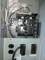
The breaker appears to be installed per manufacturer's requirements (neutral pigtail to box neutral which is not bonded to the ground at this panel, heater hooked up to the 2 load lines and ground but not the load neutral on the breaker - neither heater utilizes a neutral).

Thoughts on what I should check next?

Thanks!
While the heater element is 220v, the
I have a 10ft above ground pool. New electrical panel was just installed and I'm trying to get a heater working. I've tried both of the two heaters below (one at a time):
www.amazon.com/dp/B09983WFKQ
www.amazon.com/dp/B07XC58V5K

Both of them immediately trip the breaker not when the breaker is flipped "on" but when the heater element kicks on. They are being wired (again only one at a given time) to a brand new 20a GFCI breaker:
www.lowes.com/pd/Siemens-QP-20-Amp-2-Pole-GFCI-Circuit-Breaker/50195863

The breaker appears to be installed per manufacturer's requirements (neutral pigtail to box neutral which is not bonded to the ground at this panel, heater hooked up to the 2 load lines and ground but not the load neutral on the breaker - neither heater utilizes a neutral).

Thoughts on what I should check next?

Thanks!
Regardless of which you get to work, put the heaters in a weather-protected enclosure. Those don't look like outdoor equipment (first one says so in the description).
Your pool will/does have about 2000 gallons of water. From the description on the second:
"Suitable For: Max 2CBM(528 gallon) Hot Tub & Swimming Pool"
The first one listed is 33% smaller in capacity. You may be spending money and getting no results.
 
While the heater element is 220v, the

Regardless of which you get to work, put the heaters in a weather-protected enclosure. Those don't look like outdoor equipment (first one says so in the description).
Your pool will/does have about 2000 gallons of water. From the description on the second:
"Suitable For: Max 2CBM(528 gallon) Hot Tub & Swimming Pool"
The first one listed is 33% smaller in capacity. You may be spending money and getting no results.
Definitely building an enclosure. Once I get something working.

I know that they aren't going to be providing much heat given the size of the pool but I'm not wanting much. I have low expectations :)
 
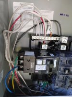
You don’t have a neutral wire going to the bus terminal main lug, is one of those other white wires to the main? Your gauge appears very small feeding the hot bus terminals. Where does the green and blue go? Green should really only be used for ground.
 
Red,

If the unit that the 240 volt GFCI breaker is protecting has no neutral, then you don't connect the pig tail to the neutral bus.

As a test, disconnect the neutral pig tail and see if your heater still pops the breaker. If it does not, then press the test button and ensure the breaker pops.

If the neutral bus bar has nothing else connected to it, it would not make a difference, but you have a couple of other white wires connected to the bus and I have no idea where they go. If you have no neutral in the box, why are there wires going to the neutral bus bar???

Thanks

Jim R.
 
Last edited:
  • Like
Reactions: Poolbreh
If the unit that the 240 volt GFCI breaker is protecting has no neutral, then you don't connect the pig tail to the neutral bus.

That is not correct.

All 220V pumps, which don't have neutral lines, connected to GFCI CBs have the CB pigtail connected to the neutral bus. And they all work fine. I wired all 3 GFCI pump CBs in my IntelliCenter that way.
 
  • Like
Reactions: Poolbreh
Do you have any Smartswitch or anything else in the heater circuit?

Show us the other end of the wiring.

You have 80 amps of breakers in the panel. What is the amps of the CB feeding this subpanel and what is the gauge of the wires feeding the subpanel?
 
Last edited:
  • Like
Reactions: Poolbreh
ll 220V pumps, which don't have neutral lines, connected to GFCI CBs have the CB pigtail connected to the neutral bus. And they all work fine. I wired all 3 GFCI pump CBs in my IntelliCenter that way.
Allen,

Your system works because you actually have a neutral wire connected to your neutral bus bar. The OP does not.

In any case, it can't hurt to try what I said, just to help narrow down the problem.

Open to any other suggestions that might actually help solve the OP's problem.

Thanks,

Jim R.
 
  • Like
Reactions: Poolbreh

Enjoying this content?

Support TFP with a donation.

Give Support
If the neutral bus bar has nothing else connected to it, it would not make a difference, but you have a couple of other white wires connected to the bus and I have no idea where they go. If you have no neutral in the box, why are there wires going to the neutral bus bar???

I am assuming the white wire going to the fifth screw from the left is actually the neutral bus feed. It matches the gauge and look of the black and red hot wires.
 
  • Like
Reactions: Poolbreh
Thank you everyone for the replies! Looking at the neutral bus, the white wire that overlaps the red is the feeder neutral. It's 10 ga wire. The two white wires to the left of the feeder go to 2 120v 20a outlets. The white wire to the right of the feeder is the pigtail from the 20a GFCI breaker (which instructs you to use the pigtail under all conditions, specifically mentioning that it is necessary even if the load device does not use a neutral).

Each of the 120v outlets gets a 20a breaker. The non-gfci 20a breaker is for a 220v outlet that I don't plan to use (came with the panel that way). I only plan on running the filter pump off of the 120v outlets and the heater off of the 220v GFCI breaker. Feeder wires are all 10ga and total approximately 100ft from the main panel. Nothing I've done has tripped the breaker in the main panel.
 
Where does the green and blue go? Green should really only be used for ground.
Winner!

The yellow/green wire had a label "L1" to go with the blue's "L2" and the brown's "GND" so that's how I hooked it up (there weren't any instructions included to instruct otherwise and they aren't standard colors for the US so I went with it). I looked up some similar heaters and they all use blue and brown as the line voltage with yellow/green as ground. I swapped them around and now it works. We'll see how much heat I actually get with such a low powered heater but at least now it's working. Thanks again everyone!
 
  • Like
Reactions: Poolbreh
Thread Status
Hello , This thread has been inactive for over 60 days. New postings here are unlikely to be seen or responded to by other members. For better visibility, consider Starting A New Thread.