Surge Protection

I'd start at the start lol.
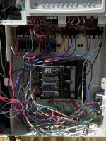
Remove the bottom breaker feeding the pcb, untangle the wires and place that breaker top right of the bus bars.
Next, Can you confirm that the 2 black, one white coming out of the flex conduit on the far right front are the surge wires?
I assume so. If that's the case move the existing double pole 20amp to bottom left of the buss bar. Take off the red and blue wires (theoretically pump) then torque to spec with #2 Robertson bit leaving only the surge wires
 
Can you snap a photo showing the full panel including the relays
It looks like your pump breaker is feeding several relays which are likely your heater and blower
 
Last edited:
Is the GFCI outlet an acceptable alternative to the GFCI breaker, or do I need a GFCI breaker for the pump? I received the Siemens GFCI breaker so I do not mind using it (I will just need to sort out my cabling first)
The gfci outlet looks like it is covering the outlet and 1 relay (light?)
You still need the pump (240v) on a gfci breaker. You can put the gfci breaker to the right so long as the pigtail is long enough to reach the nuetral bar, it's just cleaner and shorter to put it on the left.
The GFCI breaker has 3 connectors (2 for Power Load and 1 for Neutral Load) while a traditional breaker does not have a Neutral connector. My Jandy VS FloPro does not have a neutral wire, just L1, L2 and Ground. From your picture, it looks like you have something similar and I can just ignore the Neutral connector on the GFCI breaker. Is this correct?
The Neutral line (white pigtail already installed on the new breaker) needs to land on the neutral bar. Ignore the neutral LOAD port on the new pump gfci UNLESS it also happens to be feeding some 120v load thru a relay in which case that neutral will need to be wired to the breakers neutral load.
If I use the GFCI breaker for my pump, I think I will leave my other loads (lights, heater, blower) connected to the GFCI outlet, which means I will need another (standard) breaker for these loads - correct?
Lights I'm guessing are the bottom left relay being fed off of the gfci convenience outlet. I'd be willing to bet the Hester and blower are fed from the pump breaker thru one of the relays
 
One more, well for now😁
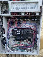
, I assume these wires are for the pcb? They are not gfci protected in their current installation under the line screw. I dont think they need to be so I would likely take them off of the gfci and give the pcb it's own $7 breaker. That way if lights etc trip that circuit the pcb is still active controlling filtration.

If that upper left tandem is truly just 2 ceiling fans you could pigtail those wires together, land the tail one one 15 and the pcb on the other saving $7 🤣
Remember only 1 wire allowed per breaker terminal screw.
1678498897831~2.jpg
 
Thank you all - that's great insights! My plan is the following:
- Analyze the wiring
- Relocate the existing double pole breaker to bottom left, and repurpose it for the surge protector
- Install the new GFCI breaker above it, to the top left
- Add a dedicated breaker to the top right side, for the PCB - I will actually get a tandem breaker to get a spare circuit
- Relocate the small 15A breaker (which I believe goes to the GFCI outlet) to the right side, below the new PCB breaker
- Relocate the tandem 15A breaker (it's actually used for 2 separate circuits) to the right side. This will leave 1 slot open on the bottom of the right side
- Relocate the surge protector and attach it directly to the panel (either on the left side, or on the bottom - you can see the surge protector wires in the bottom right of the picture).

Two remaining questions:
  1. If the Heater and Blower are on the same circuit as the Pool Pump, can they be on the GFCI breaker or do I need to put them on another circuit?
  2. I have a Stenner peristaltic pump which is attached to a dedicated GFCI outlet. That outlet is connected to one of the relays. (This way, I can program the Stenner pump). As this is a GFCI circuit already, I will isolate it from the GFCI breaker circuit if it's currently on it. I read not to add GFCI to GFCI. Is this correct?
 
Last edited:
If the Heater and Blower are on the same circuit as the Pool Pump, can they be on the GFCI breaker or do I need to put them on another circuit?
Heater and blower are good to stay on the pump gfci. They are both likely 240v, if so it should not require additional consideration. If one or both is 120v then they will have a neutral wire and that neutral will need to be moved to the LOAD neutral on the gfci breaker.
I have a Stenner peristaltic pump which is attached to a dedicated GFCI outlet. That outlet is connected to one of the relays. (This way, I can program the Stenner pump). As this is a GFCI circuit already, I will isolate it from the GFCI breaker circuit if it's currently on it. I read not to add GFCI to GFCI. Is this correct?
Gfci outlet on a gfci breaker is not an issue. In some ways it adds a layer of safety as the gfci breaker will protect from a ground fault in the wire between the panel and outlet and the outlet will protect from a ground fault locally and be easier to reset. If the outlet senses fault it will trip without also tripping the fault on the breaker.
 
OK - the inventory is complete - to be safe, I traced wires from both the line and the load sides.
  1. The 2-pole 20AMP breaker is serving:
    • The Red wing-nut which is connected to:
      • The Pool Pump Line 1
      • The Pool Pump relay LINE 1
    • The Blue wing-nut which is connected to:
      • The Pool Pump Line 2
      • The Pool Pump relay LOAD 2
  2. The 15 AMP breaker is serving the GFCI Outlet.
    • The Line side of the outlet is also powering the PCB
    • The Load side of the outlet is powering the relay for the Pool Lights (and the Neutral is connected to the Neutral for the Lights)
  3. On the relay side:
    • The top 4 relays serve the pump, heater, blower and the GFCI I use for my Stenner pump.
    • The bottom 2 relays serve the pool and spa lights
I assume that the pump is directly connected to the power (rather than the relay) because it's a VSP and the on/off is controlled via the Jandy controller. Also, the Line 2 is connected to the LOAD side of the pump relay so that the various devices cannot be powered unless the pool pump is turned on.

As my Stenner Pump outlet is 120V and it's currently on the same circuit as the 240V devices, I have 2 options: (a) Either I move the neutral wire of that outlet from the neutral bar to the neutral connector of the GFCI breaker, (b) Or I move that relay to its own circuit, as I bought a tandem. I will do (a) so that the Stenner pump does not work unless the pool pump works (but then I need to connect the hot wire of the Stenner pump outlet to Line 2 of the relay instead of Line 1 today, correct?
 

Attachments

  • Broader View.JPEG
    Broader View.JPEG
    548.3 KB · Views: 13
  • Panel.JPEG
    Panel.JPEG
    490.8 KB · Views: 13
Last edited:
  • Like
Reactions: Ahultin
assume that the pump is directly connected to the power (rather than the relay) because it's a VSP and the on/off is controlled via the Jandy controller. Also, the Line 2 is connected to the LOAD side of the pump relay so that the various devices cannot be powered unless the pool pump is turned on.
Yes but both wires from the pigtail should go to pump relay line or you're bypassing the relay? 1st and third terminal on the relay is line, 2nd and 4th is load
 
1st wire on the pump relay line terminal looks like it should be on load. As it is now pump relay only switches one phase of 240 off when the pump circuit is off
 
@Ahultin - I think the current wiring might be OK. Attached is a picture from the installation manual. They show to connect it directly to the breaker.

The doc also says "NOTE: When power alone is supplied to this pump, it will not operate. It requires a digital command sent to it by either a variable speed controller (JEP-R), an AquaLink RS controller, an AquaLink Pool Digital Assistant (PDA), or an AquaLink Z4 to operate at a chosen speed."
 

Attachments

  • Installation.JPEG
    Installation.JPEG
    563.4 KB · Views: 6
Last edited:

Enjoying this content?

Support TFP with a donation.

Give Support
@Ahultin - I think the current wiring might be OK. Attached is a picture from the installation manual. They show to connect it directly to the breaker.
@asquare , pump wiring is correct, pump relay wiring from relay 1 to relay 2 does not appear to be. As it is now the first wire in relay 1 is a jumper to relay 2 , so you have Phase 2 of relay 2 is switched based on pump relay status but phase 1 of relay 2 is constant hot.
 
Thanks for your patience with me! I think I understand what you are saying. Basically, in the same way Phase 2 is on the load side of Relay 1, Phase 1 should be on the load side of Relay 1 as well, so that Phase 1 on Relay 2 is only hot when the pump is on. The issue with the current wiring is that Phase 1 of the heater could be on and Phase 2 off if the heater relay is on but the pump relay is off. Correct?

I actually paid a pool installer to install the VSP so he should have addressed the GFCI and the wiring but I am glad I am getting all the advice!
 
Thanks for your patience with me! I think I understand what you are saying. Basically, in the same way Phase 2 is on the load side of Relay 1, Phase 1 should be on the load side of Relay 1 as well, so that Phase 1 on Relay 2 is only hot when the pump is on. The issue with the current wiring is that Phase 1 of the heater could be on and Phase 2 off if the heater relay is on but the pump relay is off. Correct?

I actually paid a pool installer to install the VSP so he should have addressed the GFCI and the wiring but I am glad I am getting all the advi
Phase 1 and 2 jumpers should be on relay 1 load going to relay 2 line.
 
CB hot wires need to connect to filter/pump relay LINE screws 1 & 3.

VS pump power wires need to connect to LINE screws 1 & 3.

Heater and SWG need to be on LOAD screws 2 & 4.

Key is VS pump and gets continuous power and is connected to LINE side screws. Heater & SWG are only powered when pump is on and are connected to LOAD side screws.
 
OK - so:
  • The 2 Hot wires go to Relay 1, Lines 1 and 2
  • The VSP wires go to Relay 1, Lines 1 and 2 (this way I can skip the Wing Nut)
  • The jumpers go from Relay 1, Load 1 and 2 to Relay 2, Line 1 and 2
I
Yes that works (and is how mine is connected to get rid of the wing nut )
 
I am done! I need to do more work on the Surge Protector - shorten the wires and move it closer to the panel, but it was getting dark. I tried to attach the surge protector directly to the panel but the 2 rows of knockout slots are too close to each other. Thank you all for the fast answers to all my questions and for your patience with my ignorance! I could not have done it without you!
 

Attachments

  • After.jpeg
    After.jpeg
    545 KB · Views: 23
  • Like
Reactions: Ahultin
I could not have done it without you!
We are glad you have found our information helpful. Please, if you can, consider making a donation to TFP. We are staffed by volunteers and are registered as an IRS 501 (c) (3) charity and donations are what keeps the forum operating without advertisements.

Support TFP!
 
  • Like
Reactions: Ahultin and JamesW

Enjoying this content?

Support TFP with a donation.

Give Support
Thread Status
Hello , This thread has been inactive for over 60 days. New postings here are unlikely to be seen or responded to by other members. For better visibility, consider Starting A New Thread.