Surge Protection

asquare

Bronze Supporter
Sep 6, 2016
56
Lake Mary, FL
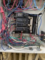
When I bought my house a few years back, the pool panel had a Type 2 Intermatic surge protector installed (model IG1240RC3). I bought a new one a few years ago when the 1st one failed, and I replicated the same installation, but I am not sure the 1st one was installed correctly. Instead of being attached directly to the box, it is beneath the panel. I can easily fix that. The other issue is that the installation instructions (attached) ask to connect it to a dedicated breaker. My problem is that I do not have any space left (see picture of my panel). The top dual breaker is for 2 ceiling fans installed in my patio, the middle breaker is for the pool and heater, and the lower breaker is for my Jandy PCB. The surge protector is currently connected to the pump breaker. I am going to call Intermatic to ask whether the current installation (same breaker as the pump) is OK, or whether that makes the surge protector useless.
I have 2 questions:
- Does anyone have a surge protector installed in a configuration similar to mine, and can you suggest a surge protector that will work with limited space
- Is there a way to protect the PCB -- I have lost 2 PCBs to power surges and would like to protect it.

Thanks!

Anthony
 

Attachments

  • 124122_ig1240rc3 instructions.pdf
    456.1 KB · Views: 10
  • Panel.JPEG
    Panel.JPEG
    528.5 KB · Views: 44
The instructions list that as a Type 1 or Type 2. As a Type 1 SPD, it can be installed without overcurrent protection, direct to the bus.

I specifically searched for a Type 1 SPD for my panel as I did not have additional breaker space.

Circuit breakers are typically only designed for a single conductor under the screw. You should confirm this with the instructions for your breaker. I would guess this is an improper installation.

I am not sure about the current installation and how that would protect, Intermatic may be able to advise. However considering that it is an improper install based on the multiple wires on each breaker terminal, I would assume they would advise it is not suitable.

--Jeff
 
Is there not additional breaker space on the right side? It appears that there are bus connections for breakers on the right.

--Jeff
 
I think you just need to get a new 2-pole, 20A breaker, and install it on the right side of the bus, then wire the SPD to that breaker.

Sorry for the multiple posts. My brain is finally catching up.

--Jeff
 
Lots going on there lol. I assume the dual pole 20 amp is your pump breaker? If so that should be gfci.
Those breakers are also not approved to have two wires under each terminal.
I am not familiar with the jandy panel but the cover should reference allowable breakers. Since you have a tandem, it is likely a quad will fit. Check if the cover states it will allow this :
If so, pull the tandem 15 . Move the 2 pole 20 to the top or better replace with this:

the surge suppressor should be at the bottom closest to the feed. Use the paired 20 amp for the surge. Put your gfci to one of the 15's. The other 15 you will add an @8" piece of wire and pigtail the two ceiling fan wires (assuming that's all they feed) onto that with a wire nut.
The suppressor below the panel is fine, the shorter the wire the better the protection.
 
The SPD must be installed to intercept any surge before it can get to other downstream circuits.

That is why when installed in a panel the SPD needs to be connected to the first breaker nearest the feeder connection. In your case the bottom of the panel.

Connecting the SPD to the middle breaker, which is incorrect for a few reasons, will not intercept any surge until after it has zapped your PCB connected to the lower breaker.

Also current NEC requires your pump CB to be GFCI, which it is not.


  • Like
Reactions: Mdragger88
Thanks a lot - so I just need a double breaker installed on the right side?
Should I move the PCB breaker above it?
Could I actually buy a GFCI CB, use it for the pump, and "recycle" the existing breaker for surge protection?
I looked up GFCI breakers - something like this?
GFCI 20AMP dual pole
 
Last edited:

Enjoying this content?

Support TFP with a donation.

Give Support
Thanks a lot - so I just need a double breaker installed on the right side? Should I move the PCB breaker above it? Could I actually buy a GFCI CB, use it for the pump, and "recycle" the existing breaker for surge protection?
I don't see why not. You want the circuit breaker for the SPD at the very bottom, since that is where the power enters.

--Jeff
 
Thanks a lot - so I just need a double breaker installed on the right side? Should I move the PCB breaker above it? Could I actually buy a GFCI CB, use it for the pump, and "recycle" the existing breaker for surge protection?
Absolutely - I would put the pump gfci breaker top left, put the 20 amp dual pole below that for the surge suppressor and move the other 2 15's to the right. That way you don't end up with a knockout empty and you can move the pcb breaker higher.
 
  • Like
Reactions: Turbo1Ton
1678191687087.pngPanel.JPEG

The circled part is what takes up more space. It will protrude further to either side. I would want to mount this breaker on the left side, so that the neutral wire is long enough to reach the neutral bus, without having to extend. It does look like you are full of wires on that side, so the right side may be the best option.

I drew in purple boxes where it would extend into. Kinda hard to see.

--Jeff
 
I bought the one below. I have not received it yet. Some reviewers say it takes more space than a standard breaker. I might therefore put it on the right side and move most breakers (except the 2 x 15A) to the right side.
20 AMP GFCI
Where you put the gfci pump breaker is less important than that you put the dual pole 20 amp for the surge suppressor at the bottom closest to where the service wires attach to the bus bars. As a just in case, I would put the pcb breaker as high up as possible (furthest from source of surge)
 
  • Like
Reactions: Turbo1Ton
Thanks - I will test for space. It seems to me that the GFCI will overlap with the Neutral bar if installed in the left side, hence the installation on the right side, but I will check and post a picture when done!
The gfci breaker overlaps the neutral bar in my install as well. They are designed to clear most of them though. 20230306_110214.jpg20230305_162413.jpg
 
Thank you @Turbo1Ton, @ajw22 and WOW @Ahultin - that's one clean install! My picture looks like a hot mess in comparison. I took another look at my panel and realized that the cabling goes through a GFCI Outlet attached to the side (you can see it on the right of my picture). I therefore have more questions, if you don't mind:
  • Is the GFCI outlet an acceptable alternative to the GFCI breaker, or do I need a GFCI breaker for the pump? I received the Siemens GFCI breaker so I do not mind using it (I will just need to sort out my cabling first)
  • The GFCI breaker has 3 connectors (2 for Power Load and 1 for Neutral Load) while a traditional breaker does not have a Neutral connector. My Jandy VS FloPro does not have a neutral wire, just L1, L2 and Ground. From your picture, it looks like you have something similar and I can just ignore the Neutral connector on the GFCI breaker. Is this correct?
  • If I use the GFCI breaker for my pump, I think I will leave my other loads (lights, heater, blower) connected to the GFCI outlet, which means I will need another (standard) breaker for these loads - correct?
Thanks a lot!
 
  • Is the GFCI outlet an acceptable alternative to the GFCI breaker, or do I need a GFCI breaker for the pump? I received the Siemens GFCI breaker so I do not mind using it (I will just need to sort out my cabling first)

Your pool pump circuit is not going through the GFCI convenience outlet on the side.

  • The GFCI breaker has 3 connectors (2 for Power Load and 1 for Neutral Load) while a traditional breaker does not have a Neutral connector. My Jandy VS FloPro does not have a neutral wire, just L1, L2 and Ground. From your picture, it looks like you have something similar and I can just ignore the Neutral connector on the GFCI breaker. Is this correct?

You still must connect the neutral pigtail on the GFCI CB to the neutral bus bar for the CB to operate.

  • If I use the GFCI breaker for my pump, I think I will leave my other loads (lights, heater, blower) connected to the GFCI outlet, which means I will need another (standard) breaker for these loads - correct?
I can't exactly follow your wiring mess but I doubt your heater or blower is going through the LOAD side of the GFCI outlet. It is used to provide GFCI for pool lights.

You need to study and understand how the GFCI outlet works. It has a LINE side that should be connected to one of the 120V CB's. Identify which one.

And it has LOAD screws that provide downstream power and GFCI protection for any devices connected to the LOAD side. Find what wires are connected to the LOAD screws.
 
Last edited:
  • Like
Reactions: proavia

Enjoying this content?

Support TFP with a donation.

Give Support
Thread Status
Hello , This thread has been inactive for over 60 days. New postings here are unlikely to be seen or responded to by other members. For better visibility, consider Starting A New Thread.