SPA heater, what would happen?

Considering we are talking about propane, please, may you let me know what are the expected drop in the 228ft 3/4” line plus the 20ft 1” line?
For the final leg, the pressure drop is about 0.5" w.c for 80 feet, or 0.625" w.c per 100 feet or 0.1875" w.c for 30 feet.

For the 228 feet at 5 psi, the pressure drop should be about 3.24" w.c.

So the pressure at the final regulator should be ok.

The final regulator seems like it is sufficient.

I am not sure why the pressure is dropping by about 5.53" w.c.

Can you see how much gas is being used per hour according to the meter?

Check the Stack Flue temperature.

1735007934245.png
 
  • Like
Reactions: Hulaomr
Where is the heater located?

If it is in a room, you need to provide an adequate air supply and proper venting for the exhaust.

Did the gas contractors say anything about the exhaust venting?

Do not operate the heater without proper exhaust venting.
 
Last edited:
The pressure at the gas valve inlet seems to be above the minimum, so it should have enough gas.

You can check the manifold gas pressure, but that is usually not necessary.

If the stack flue temperature is good and the meter is registering the correct amount of gas being used, then it is probably working correctly.

If you know the flow rate of water through the heater, you can calculate the expected temperature rise to compare to the actual temperature rise.

You can also check the temperature rise of the pool to compare to the expected temperature rise based on the pool volume.
 
For the final leg, the pressure drop is about 0.5" w.c for 80 feet, or 0.625" w.c per 100 feet or 0.1875" w.c for 30 feet.

For the 228 feet at 5 psi, the pressure drop should be about 3.24" w.c.

So the pressure at the final regulator should be ok.

The final regulator seems like it is sufficient.

I am not sure why the pressure is dropping by about 5.53" w.c.

Can you see how much gas is being used per hour according to the meter?

Check the Stack Flue temperature.

View attachment 622204
After installing a temporal vent, I could perform a longer test (~30 minutes). Below the results.

1735735200312.png1735735177500.png
StartFinish

1735735158812.png

Below a scatter chart for further analysis.

1735735266896.png
1735735634029.png
 
Where is the heater located?

If it is in a room, you need to provide an adequate air supply and proper venting for the exhaust.

Did the gas contractors say anything about the exhaust venting?

Do not operate the heater without proper exhaust venting.
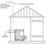
The heater is located in a room with some openings (door and window in one side) as show the diagram.

The gas contractor was focused on the meter area only.

I will look for contractors to implement a vent like the suggested in the manual (pdf).

1735737476193.png

1735737014935.png


1735737709952.png


Meanwhile, for testing I installed an 7" aluminum pipe going to the window. During the test the smell reported in previous test disappeared.
 
The pressure at the gas valve inlet seems to be above the minimum, so it should have enough gas.

You can check the manifold gas pressure, but that is usually not necessary.

If the stack flue temperature is good and the meter is registering the correct amount of gas being used, then it is probably working correctly.

If you know the flow rate of water through the heater, you can calculate the expected temperature rise to compare to the actual temperature rise.

You can also check the temperature rise of the pool to compare to the expected temperature rise based on the pool volume.

After the test of 34min, I checked the stack flue temperature resulting in 279F.

Please, may you give a reference how to check the expected temperature? The heater is using a Pentair pump 3 which include flow control.

I also noted the SPA was very hot. Around 44C according with a thermal camera, which I don't understand. Perhaps, I'm missing something here.

1735738030767.png
1735738038897.png

1735738278907.png
 
After the test of 34min, I checked the stack flue temperature resulting in 279F.
Here is what the normal exhaust temperature should be:
  • Below 250 degrees...very low
  • 250 to 290 ..................low
  • 290 to 350.................acceptable
  • 350 to 480 ..................high
  • Above 480...................error/shutdown.
279 is a little bit too low.
I also noted the SPA was very hot. Around 44C according with a thermal camera, which I don't understand. Perhaps, I'm missing something here.
44 C is 111 F.

Do you have a water temperature thermometer?

If the water temp is exceeding 104 F (40 C), then the temp sensor might be bad or the board might be bad.

You can measure the resistance of the thermistor to see if it is accurate with the temperature of the sensor.

If you have a 10k ohm resistor, you can connect it in place of the temp sensor to see if it makes the board read 77 degrees F.

Do not operate the heater with the resistor in place of the temp sensor, this is only to see if the board is reading the resistance correctly.

1735747309572.png
 
Last edited:

Enjoying this content?

Support TFP with a donation.

Give Support
1 cubic meter of propane produces about 88,905 btu.

17 cubic meters of propane is 1,511,378 btu.

17 cubic meters of propane in 34 minutes is 2,667,150 btu/hr, so that is probably not correct.

Maybe the meter is not accurate?

Are you sure that the reading is in cubic meters?

One pound of propane contains roughly 21,500 British thermal units (BTUs).

17 pounds of propane is about 365,500 btu.

365,500 btu in 34 minutes is 645,000 btu/hr, which is probably not correct.
 
The heater should produce about 400,000 btu/hr.

The heater is about 84% efficient, which transfers about 336,000 btu/hr to the water.

1 btu adds 1 degree F to 1 pound of water.

For example, 1,202 gallons of water is about 10,000 pounds of water.

So, a 1,202 gallons spa should gain about 33.6 degrees F per hour.
 
You can get a water temperature from the heater for the inlet, which is the spa water temp.

If you can get a water temp at the heater exit, you can calculate the temperature rise.

Exit temp - inlet temp = temp rise.

If you know the flow rate, you can calculate the expected temp rise.

For example, 40 gpm is 2,400 gallons per hour or about 20,000 pounds per hour.

At 40 GPM, the expected temp rise is about 336,000/20,000 = 16.8 degrees F.
1735745523222.png

1735745556688.png
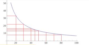
This shows the expected temp rise (Y-axis) vs. Flow in GPM (X-axis).

The minimum required flow is 40 gpm.

So, the maximum temp rise should be 16.8 degrees Fahrenheit.

A 400,000 btu/hr heater with an efficiency of 84% transfers 336,000 btu per hour to the water.

At a minimum required flow of 40 gpm, there will be 2,400 gallons of water (20,000 lbs.) that receives the heat.

Each btu raises the temperature of one pound of water by one degree Fahrenheit.

336,000 btu into 20,000 pounds of water is 16.8 degrees of temperature rise (336,000/20,000).

So, the maximum temperature rise you should ever have is 16.8 degrees Fahrenheit.

Higher flow results in a lower temperature rise.

50 gpm = 13.44 degrees temperature rise.

60 gpm = 11.2 degrees temperature rise.

70 gpm = 9.6 degrees.

80 gpm = 8.4 degrees.
 
You can use this formula to estimate the flow based on the temperature rise.

Y = temperature rise.

X = flow in gpm.

Y = 672/X

X = 672/Y.

For example a flow of 40 gpm should be a temperature rise of 16.8 degrees.

A temperature rise of 11.2 degrees should be about 60 GPM.

As you can see, flow below 40 gpm results in a big temperature rise.


Pentair_MasterTemp_Water_Manifold.jpg
1735748003205-png.622895
 

Attachments

  • 1735748003205.png
    1735748003205.png
    720.6 KB · Views: 27
  • Like
Reactions: Hulaomr
The heater is located in a room with some openings (door and window in one side) as show the diagram.
You need adequate air supply and adequate venting.
____________________________________________________________________________________________________________________________

COMBUSTION AIR SUPPLY
For indoor installation, the heater location must provide sufficient air supply for proper combustion and ventilation of
the surrounding area.

The minimum requirements for the air supply specify that the room in which a heater is installed should be provided with two permanent air supply openings; one within 12 inches (30 cm) of the ceiling, the other within 12 inches (30 cm) of the floor for combustion air, in accordance with the latest edition of ANSI Z223.1, or the National Fuel Gas code, the CSA B149.1, Natural Gas and Propane Installation Codes, as applicable, and any local codes that may apply.

These openings shall directly, or through duct, connect to outdoor air.

Note: For indoor installations where combustion air might be insufficient, see “Direct Air Intake Duct with 3-inch PVC Pipe (Indoor Installation)” below.
____________________________________________________________________________________________________________________________

 
  • Like
Reactions: Hulaomr
Do you have a water temperature thermometer?
I had one that come with the house, but seems damaged. For now, I'm using a clinical thermometer with a maximum of 42C.

1735827888979.png

Any suggestion to get a new one or any device will be fine?
 
You can measure the resistance of the thermistor to see if it is accurate with the temperature of the sensor.

If you have a 10k ohm resistor, you can connect it in place of the temp sensor to see if it makes the board read 77 degrees F.

Do not operate the heater with the resistor in place of the temp sensor, this is only to see if the board is reading the resistance correctly.
Thanks again for your suggestions.

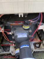
I focused on the thermistor. It measured around 9KOhm and the board get around ~25C (as expected). During the testing, I found the wire connectors were bad (please, refer to picture). I suppose the voltage reading was affected. Take advantage and change all the ones that seems similar.

After replacing the connectors, the water temperature show in the device make sense.
OldNew
1735828321485.png1735828331980.png


1735828369686.png
 
  • Like
Reactions: JamesW
Here is what the normal exhaust temperature should be:
  • Below 250 degrees...very low
  • 250 to 290 ..................low
  • 290 to 350.................acceptable
  • 350 to 480 ..................high
  • Above 480...................error/shutdown.
279 is a little bit too low.
I also replaced the wire connector for the stack flue sensor. I expect this will affect the temperature value obtained. However, at the end of the test, I was unable to get such value because the membrane panel buttons was unresponsive.

1735828531183.png

During a test, the device reported 142C (287F). It was increasing when I took the video, so I expected the temperature will increase more. I will check again once the pad is working.

1735829025377.png
 
Last edited:

Enjoying this content?

Support TFP with a donation.

Give Support
Thread Status
Hello , This thread has been inactive for over 60 days. New postings here are unlikely to be seen or responded to by other members. For better visibility, consider Starting A New Thread.