SPA heater, what would happen?
- Thread starter Hulaomr
- Start date
You are using an out of date browser. It may not display this or other websites correctly.
You should upgrade or use an alternative browser.
You should upgrade or use an alternative browser.
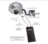
Pool Heater Manifold Gas Pressure Test with Differential Gas Pressure Manometer.
Jandy JXI Troubleshooting.
Jandy JXI Quick Reference Guide.

 www.poolheatpumps.com

Jandy JXI Troubleshooting.
Jandy JXI Quick Reference Guide.

Pool Heat Pump Owners Installation Manuals
Download an owners installation manual to assist in proper installation, operation, maintenance and service of your new heat pump or pool heater.


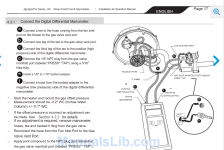
STEP 7: Test Gas Orifice Offset Pressure.
NOTE: Test the gas orifice offset pressure with the heater running using a digital differential pressure manometer.
1. Reopen the gas shut-off valve.
2. Test the offset pressure with the heater running using a digital differential pressure manometer.
Connect a tee to the hose from the fan inlet port (see Figure 20) on the blower.
3. Connect a shorter hose from the gas valve vent port to the opposite side of the tee (see Figure 20).
4. The manometer has a positive (high pressure) port and a negative (low pressure) port.
Connect a hose on the third joint of the tee to the positive (high pressure) side of the manometer (see Figure 20).
5. Remove the NPT plug from the gas valve manifold port (labeled “PRESS” “TAP”) and screw in the barbed adapter.
6. Connect one end of a hose to the gas valve manifold port and the other end to the negative (low pressure) side of the manometer (see Figure 20).
7. Start the heater and record the gas offset pressure with the heater running and the gas valve sealing cap firmly in place.
8. Read offset pressure at the manometer.
Measurement should be –0.2 ʺ WC +/- 0.1 ʺ WC
9. If the offset pressure is incorrect, adjust pressure by removing the gas valve sealing cap and rotating the plastic screw using a blunttool, such as a fl at head screwdriver (see Figure 21).
To make an adjustment, rotate 1/4 turn in either direction.
To Increase offset pressure: Turn the plastic screw clockwise.
To Decrease offset pressure: Turn the plastic screw counter-clockwise.
10. Shut down the heater at the user interface.
11. Remove the tee and replace the hoses on the top vent port.
12. Remove the barbed adapter. Apply joint compound to the NPT plug and replace to seal the vent port.

Last edited:
Note that the gas is connected to the suction side of the blower, so the manifold gas pressure is negative, which seems strange unless you have seen this before.
If the orifice is correct, maybe the gas valve is not opening 100%.
The previous gas pressure test showed a big drop from static to dynamic, but the dynamic was high enough that there should have been enough gas.
For the temperature rise test, you can install a thermistor downstream of the heater and measure the resistance to get a temperature.
For example, if the resistance measures 7,000 ohms, then you know the temperature is 92 degrees F (33.3°C).
(92°F − 32) × 5/9 = 33.3°C
You can use this formula to estimate the flow based on the temperature rise.
Y = temperature rise °F.
X = flow in gpm.
Y = 672/X
X = 672/Y.
672/(Outlet Temp °F - Inlet temp °F) = Flow in GPM.
You can also install one upstream of the heater to verify the heater water temperature reading.
Installation is easy.
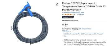
You can use a Hayward, Jandy, Pentair or Generic 10K ohm thermistor.
 www.troublefreepool.com


If the orifice is correct, maybe the gas valve is not opening 100%.
The previous gas pressure test showed a big drop from static to dynamic, but the dynamic was high enough that there should have been enough gas.
For the temperature rise test, you can install a thermistor downstream of the heater and measure the resistance to get a temperature.
For example, if the resistance measures 7,000 ohms, then you know the temperature is 92 degrees F (33.3°C).
(92°F − 32) × 5/9 = 33.3°C
You can use this formula to estimate the flow based on the temperature rise.
Y = temperature rise °F.
X = flow in gpm.
Y = 672/X
X = 672/Y.
672/(Outlet Temp °F - Inlet temp °F) = Flow in GPM.
You can also install one upstream of the heater to verify the heater water temperature reading.
Installation is easy.
You can use a Hayward, Jandy, Pentair or Generic 10K ohm thermistor.
Installing a new air temperature sensor and water temperature sensor (hayward aqua pro logic system)
I mentioned in another post that my previous pool repair person put in a new filter but somehow removed the water temperature sensor and air sensor just lying on the ground. How do I actually put in new sensors if there is no old one to remove?


1. Drill a 3/8” (10mm) diameter hole in the PVC piping and remove all chips and burrs.
2. Insert sensor until O-ring collar sits flush on the hole.
3. Position hose clamp over the sensor and gently tighten until O-ring makes an adequate seal.
Do not overtighten.

The following applies to the five-button keypads on the older MasterTemp heaters.Shorting pins 1 to 2 briefly is the same as pressing "Spa On". Pressing a button on the membrane pad shorts a pin (2 through 5) to pin 1 to make a selection. Pin 1 is the lowest pin and pin 6 is the highest pin.
1 to 2 ...spa on.
1 to 3...pool on.
1 to 4...heater off.
1 to 5...down arrow.
1 to 6...up arrow.
Pin 1 is the common wire. Shorting pins 1 to 2 briefly is the same as pressing "Spa On."
Pressing a button on the membrane pad shorts a pin (2 through 5) to pin 1 to make a selection.
Pin 1 is the lowest pin, and pin 6 is the highest pin.[40]
- 1 to 2 ...spa on.
- 1 to 3...pool on.
- 1 to 4...heater off.
- 1 to 5...down arrow.
- 1 to 6...up arrow.

Here is what the normal exhaust temperature should be:
287.6 is close to being acceptable.
- Below 250 degrees...very low
- 250 to 290 ..................low
- 290 to 350.................acceptable
- 350 to 480 ..................high
- Above 480...................error/shutdown.
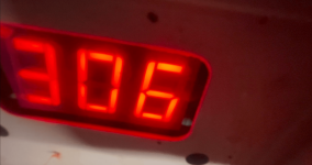
After fixing the membrane pad (temporal) and changing the cable connectors, the device is showing around 306F as the stack flue temperature. The device was ON (heating) during 15min already.
I check the orifice and it's as expected. Below some pictures.Check the orifice diameter
The color of the metal union is due to rust remover, which I applied during the maintenance of the heater. Such part was a little rust and the remover protect it for further damaged.


That is in the good range.the device is showing around 306F as the stack flue temperature.

Monitor the gas usage, the heating time of the Spa and the temperature differential from inlet to outlet.
Seems like it is working enough to keep the Spa heated.
Make sure the ventilation (Air Supply and Exhaust gas Ventilation) is sufficient for safety.
I will install a thermistor in the pipe just before the heater.For the temperature rise test, you can install a thermistor downstream of the heater and measure the resistance to get a temperature.
@JamesW, this will be ok to be used with the EasyTouch, right?
@JamesW, may I remove the auto valve in the picture? Taking in consideration the SPA pump will be running at 60GPM, I could leave the valve always open (as show the picture).
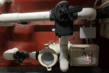
I could install the auto valve on the SPA return (as show the diagram below) coming from the filter/chlorinator?
In this way, during SPA operation, the cold water coming from the pool/filter is not going to the SPA.


I could install the auto valve on the SPA return (as show the diagram below) coming from the filter/chlorinator?
In this way, during SPA operation, the cold water coming from the pool/filter is not going to the SPA.

Make sure the ventilation (Air Supply and Exhaust gas Ventilation) is sufficient for safety.
I could install a PVC pipe to the wall outside (as show the picture). Perhaps, I will be less worry if there are some chemicals in the room.
In other hand, I don't know yet how to be sure is sufficient the air intake of current room windows.

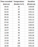
1 minute and 11 seconds is 0.85 degrees per minute, which is about 73% of the expected value.For 580 gallons, you should get about 70 degrees F per hour or about 1.16 degrees F per minute.
So, we have two methods of estimating the heater capacity at 67% and 73%, which is fairly close alignment.So, you are using about 67% of the expected amount of gas.
I would put one before the heater and one after the heater to get a temperature rise.I will install a thermistor in the pipe just before the heater.
Using that and a flow rate will get us third method of estimating the heater capacity.
The EasyTouch should have a temperature sensor before the heater.@JamesW, this will be ok to be used with the EasyTouch, right?
The PVC is for air intake/supply, not exhaust.I could install a PVC pipe to the wall outside (as show the picture).
Exhaust needs proper metal venting.
Check the manifold gas pressure.
Last edited:
You should not put unfiltered water through a heater as debris can clog the heater.
Thanks for pointing out this situation. I agree. It was the installation I found in the house: two circuits/pumps as show the diagram below.
Please, may you give me some suggestions based in the current installation. Perhaps, install another filter after the SPA pump or modify both circuits and remove one pump?
At least, all the water is filtered during normal operation (FILTER circuit)

Are you only going to want to heat the Spa and not the Pool?
You can put a filter after the Spa Pump before the heater or combine the Pool and Spa into one system with the ability to select which is operated.
You can put a filter after the Spa Pump before the heater or combine the Pool and Spa into one system with the ability to select which is operated.
I never thought in heating the pool because it was not connected. For the moment, I just want to heat the SPA only.Are you only going to want to heat the Spa and not the Pool?
Thread Status
Hello , This thread has been inactive for over 60 days. New postings here are unlikely to be seen or responded to by other members. For better visibility, consider Starting A New Thread.


