PVC Help for SWG Installation

HeyEng

0
Gold Supporter
Silver Supporter
Nov 7, 2018
1,049
Oklahoma City, OK
Pool Size
14000
Surface
Plaster
Chlorine
Salt Water Generator
SWG Type
CircuPool RJ-60 Plus
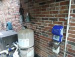
My fancy new SWG showed up today and I am anxious to get it installed. I haven't done too much work with PVC before, but with my previous experience as an airplane mechanic, I don't think it would be too difficult. The only issue is I am not sure what I "don't know" and am not sure how to proceed. I attached a picture to supplement my issue.

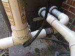
I am going to install the SWG after the heater. Currently, there is a puck dispenser (not used) that I will just toss into the shed. What I am not sure about is the unions/adapters/etc. that I have marked with the black arrows. Especially the brass colored one (far right in picture) that seems to be PVC. I understand the "long runs" that I need for installation, so my thought is Heater > SWG > Flow Switch. So, my question is how difficult will it be to remove these apparent adapters? Especially the one(s) that are on the far left going into the directional valve.

I don't think it's a difficult job, but I don't want to hack into something that will require professional help and perhaps several days of no pump/flow/etc. Thoughts and opinions are appreciated!3.jpg
1.jpg2.jpg
 
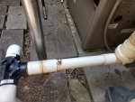
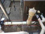
How long is area in red on the first picture..What I am wondering is if you can cut it at the plugging hole and buy a new heater adapter and just replace it from there to the valve.
It's a 30" run. Not sure about the "plugging hole"...are you talking about the plug that has a brass cap on it? And the heater adapter, is this the piece *after* the sweep fitting?
 
You can Unions for hayward heaters on Amazon, I would buy a new union and start fresh from there out.
Maybe some experts can comment on if the flow switch needs to be a certain distance before or after..

The group helped me design mine when I didn't think it was possible so see if other have ideas also.
Sounds good. Yep, there is some spacing requirements for the switch, but shouldn't be an issue.
 
  • Like
Reactions: markayash
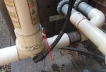
After some planning/review, I think this is how I am going to proceed. I need 13.75" between cuts. The picture here with the red lines show where I plan to cut. I will install the flow switch closest to the Jandy valve since it there is no "run length" requirement on that side. I *think* I will have enough room for the union(s) and fittings closest to the heater. Anyone see any issues with this plan? It's currently FREAKING HOT outside, so will probably knock this out nice and early in the day. :) 1.jpg2.jpg
 

Enjoying this content?

Support TFP with a donation.

Give Support
It looks like you have plenty of room. You will probably need to disconnect at the heater to provide working room for putting this together. Remember with PVC, prime both pieces, glue on both pieces, 1/4 turn minimum while putting joints together, hold in place for a count of 10.
 
  • Like
Reactions: HeyEng
After some planning/review, I think this is how I am going to proceed. I need 13.75" between cuts. The picture here with the red lines show where I plan to cut. I will install the flow switch closest to the Jandy valve since it there is no "run length" requirement on that side. I *think* I will have enough room for the union(s) and fittings closest to the heater. Anyone see any issues with this plan? It's currently FREAKING HOT outside, so will probably knock this out nice and early in the day. :)
If I recall those Jandy 3-way valves are 1.5" inside and 2" outside ... so if you needed more room you could cut all the way up to the Jandy Valve and use a 2" slip to tie back into it. that would clean up those slip couplers as well. But I would measure to be sure.
 
Last edited:
I am at a loss as to the purpose of those slip unions on that part of the plumbing. It was not originally plumbed that way, I don't think. I kind of understand if that inline chlorinator was retrofitted, but not completely.

I am not real sure. There are some oddities to this pool, for sure. I think some of it was that the original owners were going to do much more (water feature and spa) but ran out of money. Hence the "interesting" things I have seen.
 
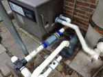
Well, in spite of some incredibly miserable heat (index was close to 115 today) and my slow work, I was able to get the SWG installed. I wasn't comfortable getting the pressure switch in along the same run as the cell, so I put it in line with the booster pump motor (that isn't used) and it seems to be happy with its location.

Hopefully over the next week, I will get it tuned in for an even *more* TFP pool! :)

All I can say is that I am very thankful to not have to turn wrenches on airplanes these days, I don't think I could stand working in this heat day after day! And a couple pictures of the completed install.IMG_20200712_193002602.jpgIMG_20200712_193323950.jpg
 

Enjoying this content?

Support TFP with a donation.

Give Support
Thread Status
Hello , This thread has been inactive for over 60 days. New postings here are unlikely to be seen or responded to by other members. For better visibility, consider Starting A New Thread.