Kaleikaumaka

Member
Feb 19, 2022
5
Arizona
Hello Everyone,

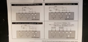
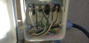
I'm trying to install a Suraielectric Digital pool timer but this wiring Diagram confuses the heck out of me. It would probably be an easy set up for an electrician. I saw a post with a gentleman installing a suraielec wifi timer and replacing the exact timer I have as well. But his previous install didn't have any wires going into the first terminal like mine. I tried to set everything else up the same as recommended in his thread but no luck. Calling out for help from the Gurus! Please help!🙏🏽🙏🏽. Pictures attached, I can take more if needed. Thanks in advance!
 

Attachments

  • 20220219_093308.jpg
    20220219_093308.jpg
    277.5 KB · Views: 45
  • 20220219_134034.jpg
    20220219_134034.jpg
    190.6 KB · Views: 45
K,

Your current timer box has 3 input conduits. We need to know where each conduit goes.

Also what is it you are trying to power and with what voltage 120 or 240 volts? (Most likely 120, but you can't really know for sure by just looking at the color of the wires.

Thanks,

Jim R.
 
I think the box has four conduits into it. Two from the bottom and left and right.
 
K,

Your current timer box has 3 input conduits. We need to know where each conduit goes.

Also what is it you are trying to power and with what voltage 120 or 240 volts? (Most likely 120, but you can't really know for sure by just looking at the color of the wires.

Thanks,

Jim R.
OK, Thanks for the replies! I'm trying to power the pump, salt cell and the pool Light which also has a gfci plug in line with it. Attached is the picture edited with tags of whats what. The salt cell wires are blocking the main power conduit so they aren't visible in the picture, attached is another picture with the main power and gfci plug. 🙏🏽
 

Attachments

  • 20220219_150526.jpg
    20220219_150526.jpg
    285.8 KB · Views: 25
  • 20220219_121235.jpg
    20220219_121235.jpg
    346.1 KB · Views: 25
K,

Your current timer box has 3 input conduits. We need to know where each conduit goes.

Also what is it you are trying to power and with what voltage 120 or 240 volts? (Most likely 120, but you can't really know for sure by just looking at the color of the wires.

Thanks,

Jim R.
I'm honestly not sure of the voltage, but it is probably just 120v. Its a double switch in the breaker box 🤷‍♂️ 
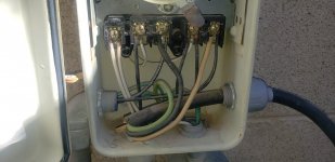
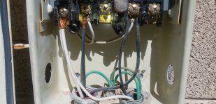
should I take a tester to it?
 
The first terminal is just used to connect together the two white neutral wires. Use a wire nut to connect the wires.

Follow lower right 240V wiring diagram.

1-> COM1
2 -> NO1
3 -> COM2
4 -> NO2

Power L from COM1 and N from COM2.

Best practice is not to put more then 2 wires under a screw. With more wires tie them together using a wire nut and a pigtail to connect all of them to a screw.

Good luck!
 
  • Like
Reactions: Kaleikaumaka
One of the things that concern me is the lower right diagram shows it expects 120 volts between L1 and L2. That is incorrect. It will be 240 volts.

I don’t know if the the timer controls are dual voltage and automatically adjust for input voltage.

If instead of connecting N to L2 you connect it to the two white wires you wire nutted you will give the timer 120V instead of 240V.
 
  • Like
Reactions: Kaleikaumaka
The first terminal is just used to connect together the two white neutral wires. Use a wire nut to connect the wires.

Follow lower right 240V wiring diagram.

1-> COM1
2 -> NO1
3 -> COM2
4 -> NO2

Power L from COM1 and N from COM2.

Best practice is not to put more then 2 wires under a screw. With more wires tie them together using a wire nut and a pigtail to connect all of them to a screw.

Good luck!
Awesome thanks for you help! Working like it should✊🏾
 
Thread Status
Hello , This thread has been inactive for over 60 days. New postings here are unlikely to be seen or responded to by other members. For better visibility, consider Starting A New Thread.