Pentair EasyTouch System Alerts

ZRacer8327

Member
May 21, 2021
12
Orange County, CA
Pool Size
28000
Surface
Plaster
Chlorine
Salt Water Generator
SWG Type
Pentair Intellichlor IC-40
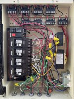
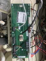
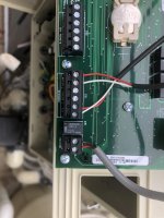
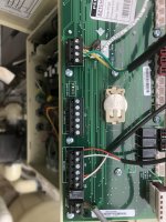
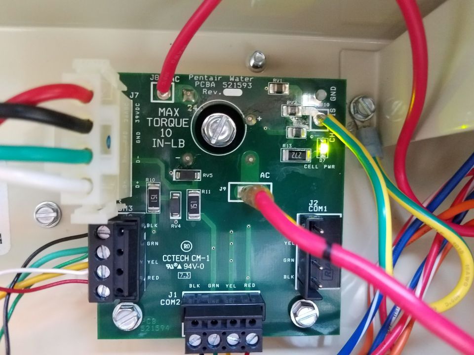
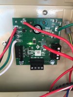
Hello Everybody! I am new to the forum and hoping I can get a little help. I just completed a backyard remodel and added a Pentair EasyTouch Automation system with Screenlogic2, Intellichlor IC40 SWG and an additional pump (Whisperflo 1 1/2 hp) for some water features. My current pump is a 2015 Intelliflow 3hp Variable Speed pump . Since the new plaster is less than 30 days old, I have not added salt yet. The SWG is connected, but I have it off until after I add salt. My problem is that I keep getting system alerts saying "Pump 1: Power Outage Alarm" and "Pump 1: Communication Lost" as well as "Chlorinator: Communication Lost." This only happens when I turn the pump off. My understanding is that the pump should have constant power, so I am guessing that something is wired incorrectly causing the pump to lose power when turned off. Also, when I put the system in Service mode, the pump turns completely off and I have no option to manually control the pump with the pad on the pump. Is this normal, or should I be able to manually control the pump when in service mode? I have attached a picture of the wiring in the panel, but not sure if anybody is able to diagnose with the picture. I did see another thread with a similar question, but my panel has a few more things going on, and I don't want to mess with it without getting some guidance. The pool company is supposed to come out and look at it, but if it is an easy fix, I would rather fix it myself. If not, at least I will have some knowledge when discussing with the installer.

Thank you!
 

Attachments

  • Pentair EasyTouch Control Panel.jpg
    Pentair EasyTouch Control Panel.jpg
    573.5 KB · Views: 16
Your pump is wired to the LOAD side of your filter/pump relay when it should be connected to the LINE side screws so that it gets constant power.

Your SWG transformer looks like it may be wired to one of the CBs when it should be wired to the LOAD side of your filter/pump relay.

Since your conduits where the wires come up are not labeled and you have a rats nest of wires in the middle of the panel I can't say exactly what wires to move. If you can identify the specifc wires for the pump and SWG transformer then we can talk about where to move them to.
 
Last edited:
  • Like
Reactions: ZRacer8327
Z,

I tend to agree with Allen, but I can't really follow the wiring though the mess in the middle..

When you go to the Service Mode, if your pump has no power.. Then it is incorrectly wired to the Load Side of the Pump/Filter relay..

If your salt cell has any lights on, when in the Service Mode, then it is not correctly wired to the Load side of the Pump/Filter relay as it should be per the warning on the SWCG's Transformer..

I concur this is most likely the reason for your alerts..

Thanks,

Jim R.
 
  • Like
Reactions: ZRacer8327
Thanks for the info guys. Let me decipher the wiring to try to clear things up a little.

Conduit (From left to right)
1) Power for the outlet on the side of the panel.
2) Electrical lines that run to the outlets around my deck
3) Electrical from the slide/waterfall pump
4) Heater
5) Filter pump

CB reference 1-6 starting from the top down.

Filter Pump Relay
Line 1 - Red->CB3 Load Pwr
Line 2 - Red->CB3 Load Pwr
Load 1 - Red->Heater, Blk->Filter pump
Load 2 - Red->Heater, Blk->Filter pump

Aux 1 Relay (Terminals from left to right)
1) Red -> CB4 Load Pwr
2) Blk -> Filter pump (connects to the red wire from the pump...must have ran out of red wire and just used blk)
3) Red -> CB4 Load Pwr
4) Blk -> Slide/waterfall pump

Control Transformer
Yellow -> CB6 Load Pwr
Black -> CB6 Load Pwr

SWG Transformer
White -> CB5 Load Pwr
Yellow-> CB5 Load Pwr
 
Z,

Did you run to two tests I suggested in post #3.. if so what were the results??

Thanks,

Jim R.
Hi Jim,

Yes, I did run those two tests. When in service mode, the pump has no power, and the SWG still has power (Flow and Salt lights are red).
The filter pump wires do go to Load 1 & 2 of the of the filter pump relay. Do I just move them to Line 1&2? The wires currently at Line 1&2 go to the CB. Do I leave those?
The white and yellow from the SWG transformer go to the CB. Should I move those to Load 1&2 on the filter relay? Do I leave the heater wires currently on Load 1&2?

Thanks!
 
Z,

The pump must get constant AC power.. You can do that by taking the wires that go to the pump off of the load side of the pump/filter relay and put them on the line side of the same relay..

The SWCG cell must NOT have power when the pump is not running.. You need to remove the White and Yellow SWCG transformer wires from the circuit breaker and put them on the load side of the pump/filter relay.

Not sure why you have the heater getting power from the pump filter relay?? You can if you want, but I don't see the point, or what it accomplishes. If this were my system I would just power the heater direct from a circuit breaker.. (You could use the one you just took the SWCG wires off of..) But, that is up to you.

Thanks,

Jim R.
 
  • Like
Reactions: ZRacer8327
Z,

The pump must get constant AC power.. You can do that by taking the wires that go to the pump off of the load side of the pump/filter relay and put them on the line side of the same relay..

The SWCG cell must NOT have power when the pump is not running.. You need to remove the White and Yellow SWCG transformer wires from the circuit breaker and put them on the load side of the pump/filter relay.

Not sure why you have the heater getting power from the pump filter relay?? You can if you want, but I don't see the point, or what it accomplishes. If this were my system I would just power the heater direct from a circuit breaker.. (You could use the one you just took the SWCG wires off of..) But, that is up to you.

Thanks,

Jim R.
Hi Jim,

You are a life saver and were spot on with this. I switched the pump wires and now the power to the pump does not get cut when I turn it off, service mode works, and there are no more alerts.

I rewired the SWCG and now that seems to be operating as it is supposed to. Turns off with the pump and no more communication alerts.

Last, I took your advice and ran the heater to the CB which makes sense to me as well. Not sure why it was run to the relay.

Everything seems to be working correctly now. In a couple days I will add salt and should be set.

Thanks again for your help, and also thank you for your service to our country!

-Jason
 
  • Like
Reactions: Jimrahbe
Hey Jim,

Came across another concern. I notice that when the heater turns off, the system is turning off power to the heater, instead of just turning the heater off. Also, when in service mode, the heater has no power. Like the pump. shouldn't the heater have constant power? I moved the heater wires to the CB per your suggestion. Any ideas what could be wrong?

Thanks,

Jason
 

Enjoying this content?

Support TFP with a donation.

Give Support
Jason,

Is the heater actually losing AC power or is the screen just going blank??

If the AC power to the heater comes directly from a circuit breaker, then the EasyTouch can't turn that AC on or off..

How is the heater connected to the EasyTouch? RS-485 or the two wire fireman's switch??

Show me a pic of the back side of the EasyTouch board...

Something is wrong, just not sure what?

What specific model Rheem heater do you have??

Thanks,

Jim R.
Well, the screen goes blank, so I was assuming it was losing power. The reason I say that is because prior to automation, the screen was always on. Also, shouldn't I be able to manually control the heater if in Service mode?

The heater is connected via the two wire switch. Pics of the board attached.

The heater is a Rheem P-M407.
 

Attachments

  • EasyTouch Board 1.jpg
    EasyTouch Board 1.jpg
    419.4 KB · Views: 9
  • EasyTouch Board 2.jpg
    EasyTouch Board 2.jpg
    310.1 KB · Views: 9
  • EasyTouch Board 3.jpg
    EasyTouch Board 3.jpg
    403.7 KB · Views: 9
Jason,

Short the two wires going to the gas connection and see if the heater screen comes back on.. If it does we at least know what direction to look.

If the Screen does not come back on then you need to see if you actually have AC power to the heater.

I don't know for sure, but I doubt the heater will work in the Service mode.. When in the Service mode, most automatic things done by the main board will not work.. I don't have a heater so I have never tried to turn it on while in the Service mode.

Are you sure that the wires you connected to the Circuit Breaker actually go to the heater??

Thanks,

Jim R.
 
Hi Jim,

I ended up finding a manual online and read about the remote mode. I am going to try that tomorrow. The heater works, but when it gets to temp, the system seems like it is cutting power to the heater rather than just switching of the burner. I will try switching to remote mode and see if that fixes it.
One more question (seems like I keep saying that). Started up my SWG and it is working fine. However, it will not connect to the EasyTouch system. I get a “Chlorinator: Communication Lost” every time it is one. I get no salt water reading and if I switch the chlorination percentage, it does not register at the generator. Any ideas?
 
Z,

There has to be a cable between the J20 com port and your SWCG power supply card..

Do you have an Internal power center for your SWCG or an External power center?

If you have an Internal power center on the back wall of the EasyTouch, behind the drop down LED panel, you should see a card like this...


Thanks,

Jim R.
 
Z,

Your system came with a cable that connects J20 on the main board with JP2 on the "surge" card.. What happened to it???

If you can't find it, then you need to buy a short piece of a 4-wire 22 gauge cable and connect one end to the 4 pins of J20 with the same pins on JP2 or JP3 or JP4 they are all electrically the same...

This will allow your system to "talk" to the cell..

Who wired your unit???

Thanks,

Jim R.
 
  • Like
Reactions: ZRacer8327

Enjoying this content?

Support TFP with a donation.

Give Support
Thread Status
Hello , This thread has been inactive for over 60 days. New postings here are unlikely to be seen or responded to by other members. For better visibility, consider Starting A New Thread.