New build pump pad

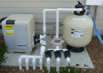
I will be installing a pool this spring, and I have looked over a ton of different setups. On paper I have put something together like this picture below.

3 - Input - 2"
4- output - 1-1/2"
All sweep 90's. My thought instead of using 2 90's going to the heater, there I would use to 45's since long sweep 90's is less head than using two 45's but going to the heater has 2 90's.

I also wanted to put values on each of the out put side.

Is there anything I should do different ?
1579055330657.png
 
Although many installs don’t have it IC40 Install Manual says “Note: For best flow sensing, provide at least 12"-18" of straight pipe in front of the cell inlet.” Best to provide a bit of straight run coming into the SWG.

The head difference of 45s vs 90s is immaterial to the operation of your pool system.

As Kim said, Heater Bypass - Further Reading

 
Last edited:
Although many installs don’t have it IC40 Install Manual says “Note: For best flow sensing, provide at least 12"-18" of straight pipe in front of the cell inlet.” Best to provide a bit of straight run coming into the SWG.

The head difference of 45s vs 90s is immaterial to the operation of your pool system.

As Kim said, Heater Bypass - Further Reading

I seen that and trying to figure out how to make that 12" straight pipe prior to the IC40. Other issues is a few years ago they flipped their design where the flow now goes the other direction, so I know the display will be backwards.

I agree on the heater by pass.

Thanks
 
Get as much of a straight run into the IC40 as you can. Don’t do a 90 right into the SWG as in the pic in your first post.
 
Get as much of a straight run into the IC40 as you can. Don’t do a 90 right into the SWG as in the pic in your first post.
Thank you!

Only reason I'm going with the IC40 is because I have had it on my past pool with good results. When I was looking at the setup, I was shocked it had the 12" straight pipe in the manual. My last pool I had installed the installer didn't do that, maybe 4"
 
From memory and removing mine every fall I thought i had a dead 90 coming out of my heater to the SWG. When I looked at it specifically to see, it was a union, 3inches of pipe, the 90, 3 more inches and another union. Maybe the sum of the parts equals a foot, or the PB just knew it would work for me, but there are systems that it won’t work for so the manufacturers recommendation is always quoted.
 
  • Like
Reactions: ImLon2
From memory and removing mine every fall I thought i had a dead 90 coming out of my heater to the SWG. When I looked at it specifically to see, it was a union, 3inches of pipe, the 90, 3 more inches and another union. Maybe the sum of the parts equals a foot, or the PB just knew it would work for me, but there are systems that it won’t work for so the manufacturers recommendation is always quoted.

The straight line on the output side of the SWG does not count. The straight pipe on the input is to get rid of turbulence of the water so the water smoothly flows over the cell plates.
 
  • Like
Reactions: Newdude
The straight line on the output side of the SWG does not count. The straight pipe on the input is to get rid of turbulence of the water so the water smoothly flows over the cell plates.

Yes I have 3 inches and a 90 on both sides. The after 90 goes right into the ground, but I was referring to the before 90.
 

Enjoying this content?

Support TFP with a donation.

Give Support
2,

Not having the 12" of straight pipe might have a very slight difference in operating pump speed, but in the big picture I doubt it will make enough of a difference for you to even notice. My system has a 90 degree fitting about 2" from the cell's union and it works just fine.

Put in 12" if you can, but if not, I would not go crazy to do it.

Thanks,

Jim R.
 
I just looked at the manual for the heatpump I'm getting Looks like the plumbing will actually hook up behind the unit near the bottom, If that's the way I set in in place. Which then it will give me plenty of room for my 12-18" straight pipe.

This layout will also allow me to have bypass from the heater. Will the check valve be enough going back into the heater, or should I move the check valve to the left and put a ball valve where the check valve is?
1579116883163.png
1579116905327.png
1579116947927.png
 
I would put in one 3 way diverter valve at the T for the heater bypass. That ensures that someone does not misset one of the two valves they would need to turn. Also ball valves get sticky over time, the handles can break, and are difficult to repair.

I would also use diverter valves and not ball valves on all of your suction and return lines.

The yellow arrows show the normal water flow through the heater. The blue arrows show the water flow when the heater is bypassed.

Heater bypass.png
 
  • Like
Reactions: ImLon2
I would put in one 3 way diverter valve at the T for the heater bypass. That ensures that someone does not misset one of the two valves they would need to turn. Also ball valves get sticky over time, the handles can break, and are difficult to repair.

I would also use diverter valves and not ball valves on all of your suction and return lines.

The yellow arrows show the normal water flow through the heater. The blue arrows show the water flow when the heater is bypassed.

View attachment 125218
Thanks!!

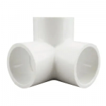
Should I use this bring the bypass into the return line after the heater eliminating the Tee, and 90", and making it one fitting? Never used one of these before.
1579119615102.png

I was debating diverter valves. Do they allow more flow than the ball valves?
 
I don't think it makes a difference if you use the corner fitting or a T and a 90 fitting.

Nothing to debate on diverter vales. They are more reliable and maintainable then ball valves. Ball valves, especially ones rarely turned, will stick over time. Flow is no different.
 
You have 7 pipes coming out of the ground. What is each for?

Where are you going to run the waste line from your filter to?
 
In addition to the unreliability of ball valves, another issue is: the way you've got them in place, an inquisitive little hand could shut down flow entirely, before and/or after your pump, and that would be bad. Diverter valves can be used instead, to get the same amount of control, but without ever being able to shut things down completely. The only reason you'd want to do that is if your equipment pad was below your water line (like if you had to replace the pump but didn't want to drain your pool to do so).

Man, did I get my hide tanned for messing with valves in my uncle's pump house (for his farm). He didn't seem to appreciate the fact that I managed to save the Starship Enterprise by way of my masterful manipulation of those controls. What a grump he was! ?
 
  • Haha
Reactions: Newdude
I see you've replaced the ball valves, but those new ones could still be set to starve or cut off the pump from the pool. Sorry, I can't suggest the schematic for the diverters for you (others here can), but I believe you'd actually need less of them, as another benefit.
 
I see you've replaced the ball valves, but those new ones could still be set to starve or cut off the pump from the pool.

Diverter handles can be tightened down with the screw in the middle so they can't be easily turned without knowing to loosen the screw.

Or some folks remove the handles so they cannot be turned. When my pool is closed for the winter the handles on the closed valves are removed.
 

Enjoying this content?

Support TFP with a donation.

Give Support
Thread Status
Hello , This thread has been inactive for over 60 days. New postings here are unlikely to be seen or responded to by other members. For better visibility, consider Starting A New Thread.