Hi,
I don't use forums often, so please forgive me if I don't follow proper procedure. I had my pool equipment upgraded with Pentair Intellicent Control System, Pool & Spa upgrade kit. I also had the iCHLOR 30 with PWR Center installed. I noticed that the iCHLOR never turns off.
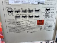
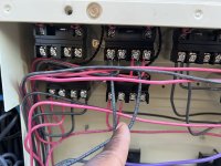
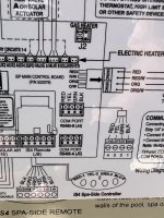
I've seen that when you put the system into service mode, the unit should turn off with the pump. That doesn't happen, I open the main control center, and noticed that there is nothing connected to the pump/filter relay. I also can't determine which relay the pump is running on.
I can provide pictures if needed. I contacted the service company that did the install, and they are scheduling me 2 weeks out, plus and extra service charge. I would love to firgure it out, with using them and paying extra.
I previous had the pentair intellitouch system i9+3. Any help will be greatly appreciated.
Thank you,
Ray
I don't use forums often, so please forgive me if I don't follow proper procedure. I had my pool equipment upgraded with Pentair Intellicent Control System, Pool & Spa upgrade kit. I also had the iCHLOR 30 with PWR Center installed. I noticed that the iCHLOR never turns off.
I've seen that when you put the system into service mode, the unit should turn off with the pump. That doesn't happen, I open the main control center, and noticed that there is nothing connected to the pump/filter relay. I also can't determine which relay the pump is running on.
I can provide pictures if needed. I contacted the service company that did the install, and they are scheduling me 2 weeks out, plus and extra service charge. I would love to firgure it out, with using them and paying extra.
I previous had the pentair intellitouch system i9+3. Any help will be greatly appreciated.
Thank you,
Ray