Intellitouch Indoor Control Panel getting no power and Pump not responding - other actions work?

robdog511

Member
Jul 14, 2021
6
Bakersfield, CA
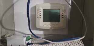
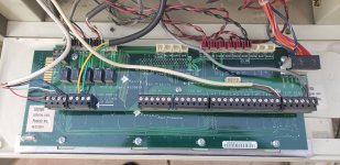
Hello, first time post here. I recently moved into a home with an Intellitouch I9 system installed. I have never worked with pool automation before but I think I am getting the hang of it. Anyways, yesterday my pool people came out to service the pool. Prior to this, my intellitouch system was working fine. However, when the pool people left I noticed that they left the system in timeout mode with my waterfall running. I thought this was odd cause the guy usually just does his thing, sets it back in auto and takes off. It turns out there were 2 pool people that came today and they weren't my regular guys which is why it was different. Well, I go out there and set the system back to auto and try to access the indoor controller through the pentair app and it wasn't showing up. Weird I thought. So I went to the controller and its getting no power anymore. The thing is just dead. I started messing around with the intellitouch in service mode and realized that Everything is working EXCEPT for the Filter Pump and the indoor controller. No issues anywhere else. My system is still running through the cycles just fine, though the pump cycle hasn't yet attempted to run today, but I am thinking that it will fail. Whenever I try to run the pump from the intellitouch I just hear a click with no start up. If I put the system in service or timeout mode I am able to control my pump manually at the pump itself so there isn't any issue there. Anyone have any insight as to why the indoor controller and pump control on the intellitouch itself would fail together? I pulled the intellitouch apart and nothing seems disconnected anywhere which would be odd if it was since nothing should have changed. Maybe its a breaker problem or something? Not sure where to start troubleshooting this, but any help would be appreciated.
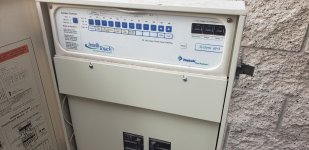
20210715_080316.jpg20210715_082454.jpg20210715_082339.jpg
 
511,

I assume you have an IntelliFlo pump... If so, with the system in Auto, tell me what the pump's display says.. It should say.. "Display not Active"... If it does not, it means you have most likely lost your Com port..

Let's get some feedback from Tom, our remote expert.. Calling @ogdento

Thanks,

Jim R.
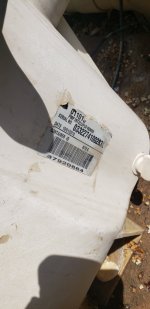
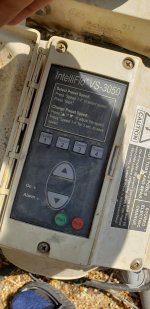
Thanks for the help Jim. My pump is pretty old so it appears there is no display screen. I attached an image of what it looks like.

After what you said and looking more into it, I do see the comm ports could be the problem. Can I somehow attach a multi meter to those ports in a way to see if they are sending signals? I figured out that the left port is connected to my Indoor Controller while the right port must be going to the pump itself.20210715_101311.jpg20210715_101321.jpg Thanks!
 
Last edited:
511,

Do you have a wired indoor panel and ScreenLogic.

If so, if you can use ScreenLogic to turn on a light and the light comes on in the pool, then your com port is ok.

I would disconnect the wired remote and see if the pump starts to work.

The remote gets DC voltage and a data signal.. You can measure the DC voltages if you wish, but not the data signal.

Measuring between the Black and Red pins of the com port connector should give you +15 VDC..

I don't have an wired indoor remote, but "assume" it powers up from the +15 from the IntelliTouch..

Thanks,

Jim R.
 
Hey Jim,

I have only that indoor wired control panel you see in the first pic, which my screenlogic connects to. I can't connect to it with screenlogic because it doesn't show up in the application anymore.

I disconnected the wired indoor panel and the pump would not come on via the intellitouch button still.

However, at 11AM this morning my pool pump did come on as scheduled, so the communication between the intellitouch and the pump seems intact. I haven't had time to check the power being sent to the Indoor panel from the intellitouch yet but should be able to shortly and will update when I can.

If it ends up being a dead indoor panel, I may just rig together my own indoor panel using some code on github and a raspberry pi because those things appear to run around $500 plus dollars and they dont really do much. You can build your own for much cheaper.

Thanks again for all the help. Feels like I am getting there.
 
Hey Rob,
Just so I understand your config... on your i9 personality board, I see the pump connected to the right comm port and the cable that (i think) goes to the indoor controller/screenlogic on the left port... the comm port is just an rs485 bus, so I imagine the screenlogic and indoor are connected to the same cable that runs to the left comm port?

And as far as I know, you can never turn the pump on from the outdoor panel... when you set the outdoor panel to service mode, you effectively tell the intellitouch not to control the pump anymore and you have to run the pump from it's own panel.

If the screenlogic isn't showing up in the application, i think that means it's not able to connect to your network via ethernet... is it getting power? The indoor could be causing a problem here... when the indoor unit won't turn on but you hear a faint high pitch noise coming from it, you'll frequently see the voltage from the black to red wires on the comm port is below 7 or 8 volts because something connected to the it is drawing too much current. It should be 10-15 volts dc. The screenlogic won't run if it's less than 8 or 9v.

You mentioned you disconnected the indoor panel... did you disconnect the Screenlogic as well? What @Jimrahbe means is to disconnect everything except the screenlogic... i.e. unplug the comm terminal block for the pump, and take the indoor controller off of the cable that goes to the screenlogic. Shut the power down before doing this because if you short the data lines you'll break your comm chip. At this point, you want to power back up and try to use the screenlogic to turn an aux circuit on/off... you should see the corresponding LED on the outdoor panel. If you can't then there's something up with the comms... either the cable has been messed with or the pool guys have done something to damage the port. correction: i just re-read one of your posts that says the outdoor board is still controlling the pump... so the comms to the outdoor board seem ok. either the cable to the indoor unit is bad or shorted, or the indoor unit and/or screenlogic is bad and drawing too much power - causing the other not to run. I'm wondering if somehow the comm port on the indoor unit died and is dragging the whole thing down.

Tom
 
Last edited:
the indoor unit and/or screenlogic is bad and drawing too much power - causing the other not to run. I'm wondering if somehow the comm port on the indoor unit died and is dragging the whole thing down.
Tom,

That would be my guess...

Is there anything that can be done to repair or troubleshoot the indoor control unit???

I think you told me this once before, but I have forgotten.. Do the two com port connection on the IntelliTouch each have their own RS-485 chip sets? I assume there is still just one com port.??

Thanks,

Jim R.
 
@Jimrahbe, to trouble shoot the indoor units i connect it by itself to a bench supply at 11vdc, and measure the current draw. it should be around 160mA (+/- 20-30, depending on the brightness settings for leds/backlight). If it's much over that, and the panel otherwise works (can use the buttons/menus) then the comm circuitry is likely fried. If it doesn't boot up at all it could be anything, but it's usually the lcd drive voltage (there's a boost converter to go from 5v to ~22v to run the display, and the caps tend to die).

The two ports on the i7/i9 are in parallel... black-black, yel-yel, grn-grn, red-red and go to the same spot on the main board. There are two comm chips on later revisions of the mainboard but they're both connected to the same bus. I'm not sure what the firmware does differently if it sees 1 or 2.
 
  • Like
Reactions: Jimrahbe
Hey Rob,
Just so I understand your config... on your i9 personality board, I see the pump connected to the right comm port and the cable that (i think) goes to the indoor controller/screenlogic on the left port... the comm port is just an rs485 bus, so I imagine the screenlogic and indoor are connected to the same cable that runs to the left comm port?

And as far as I know, you can never turn the pump on from the outdoor panel... when you set the outdoor panel to service mode, you effectively tell the intellitouch not to control the pump anymore and you have to run the pump from it's own panel.

If the screenlogic isn't showing up in the application, i think that means it's not able to connect to your network via ethernet... is it getting power? The indoor could be causing a problem here... when the indoor unit won't turn on but you hear a faint high pitch noise coming from it, you'll frequently see the voltage from the black to red wires on the comm port is below 7 or 8 volts because something connected to the it is drawing too much current. It should be 10-15 volts dc. The screenlogic won't run if it's less than 8 or 9v.

You mentioned you disconnected the indoor panel... did you disconnect the Screenlogic as well? What @Jimrahbe means is to disconnect everything except the screenlogic... i.e. unplug the comm terminal block for the pump, and take the indoor controller off of the cable that goes to the screenlogic. Shut the power down before doing this because if you short the data lines you'll break your comm chip. At this point, you want to power back up and try to use the screenlogic to turn an aux circuit on/off... you should see the corresponding LED on the outdoor panel. If you can't then there's something up with the comms... either the cable has been messed with or the pool guys have done something to damage the port. correction: i just re-read one of your posts that says the outdoor board is still controlling the pump... so the comms to the outdoor board seem ok. either the cable to the indoor unit is bad or shorted, or the indoor unit and/or screenlogic is bad and drawing too much power - causing the other not to run. I'm wondering if somehow the comm port on the indoor unit died and is dragging the whole thing down.

Tom
Hey Tom, thanks for the reply.

You are right in that on the personality board, the right comm port is going to the pump, the left is going in the home to the garage and powers a screenlogic interface adapter and an indoor control panel. I'm pretty sure they are both connected together for reasons below. I didn't realize that when saying "Screenlogic" you meant the protocol adapter but now I understand.

I thought I could hit the filter pump button on the outdoor panel while in service mode to turn the pump on and off, but I understand what you are saying now so that was my bad. Just curious, why is that button there then?

The screenlogic isnt showing up in the application either when power is going to it. I actually went and looked at it and there was 0 power to that as well. I took both rs485 connectors off of the screenlogic and the indoor control panel and checked them with a multimeter as Jim recommended. When both are unplugged, either reads 17 VDC pretty constantly. If i plug one into either device, it then reads around 2 for that remainder voltage on the opposite plug. I even went as far as switching which comm port on the intellitouch is powering the stuff inside, but its the same outcome. So I think the comm port is messed up. Also, my pool is currently on its cycle so when I shut the power off to the pool equipment and turned it on when the comm port to the pump was disconnected, that pump still came back on like it was supposed to. I assume that comm port only controls the speed which is why the pump continued to run?

I unplugged the comm block for the pump and that didn't change anything. So now the issue is that I cannot get the Indoor Control Unit nor the Screenlogic to power on at all in any case. These devices are stupidly expensive. I am software developer and considering buying a USB to RS485 adapter and running nodejs-poolControlller on github. The adapter I am purchasing is powered on the usb side and has 3 connections on the RS485 side, assuming ground and both data connections. If the power is the problem and the communciation for the intellitouch comm port is still intact, I would think I could use this to test communication to the Intellitouch once I receive the adapter. Do you think this makes sense? I just do not want to drop hundreds of dollars on a Control Panel that looks like a thermostat from the 1990s and hundreds more into another interface adapter when I already have a raspberry pi and the RS485 adapter is like 15 bucks.

I may look at troubleshooting the indoor unit still, and hopefully the comm port on the intellitouch is not unusable if that is the culprit. Would the only option then to be replace the entire board, or is there a way to desolder and resolder a comm chip or something back to that board?

Thanks again, appreciate all the helpful information!
 

Enjoying this content?

Support TFP with a donation.

Give Support
switching which port you connect to won't matter - they're the same port, pentair just gives you two connectors.

but your testing sequence seems right... if you plug the screenlogic in without the indoor panel (and vice-versa), and in both cases the voltage drops to 2vdc... as long as there's no shorts on the cable then I'd say both devices are damaged.

you can remove and replace the comm chips in the screenlogic (protocol adapter) and in the indoor panel. total parts price from mouser is going to be less than shipping...

the part number for the screenlogic device can be found here:

the indoor unit has an intersil or a maxim part, see here:
 
Tom,

Correct me if I am wrong.. The +15 VDC is just a power supply voltage right?? The RS-485 chips just control the + and - Data lines (Green and Yellow)

Are you saying that if the RS-485 chips goes bad it can load down the +15 ???

On the surface this make no sense.. If the main board was bad and loading down the +15, then when both the ICU and ScreenLogic were disconnected the voltage would still be low.

511,

Where do the 4 wires go from the left com port?? Somehow they have to be tied together if they end up going to both the ICU and the Protocol adapter????

Did your ScreenLogic/Protocol adapter ever work??

Thanks,

Jim R.
Hey Jim,

The 4 wires on the left com port go down from the pump and show up in the garage in a box. There are 2 sets here, one for the protocol and the other for the indoor panel. Both worked fine since we moved in and have been since we moved in for the last month. I could work the pool equipment in the garage on the indoor panel or use my phone and connect through my router to the protocol connection.

So to clarify my testing, I have these two devices in my garage with 2 RS485 plugs. If both are unplugged, both plugs read 17 VDC on the multi meter. If I plug one in to either the indoor panel or the protocol adapter, the one opposite that is not connected to anything reads 2 VDC. I assume this is because the 15 VDC is being drawn from whatever is plugged in. If this is the case, should one of these never have worked since both require 15 VDC and are piggybacking off each other?
 
@rstrouse - the socketed chips are relay drivers, not transceiver chips... but they too can fail and cause a high draw on the system transformer

@Jimrahbe - you are correct, the 15v is just a supply for anything connected to the comm port - including the comm chips which have to be powered. when the comm chips die, it's frequently from a shock/surge/lightning-bolt to the data lines... those are just drivers/receivers that are made up of a pile of transistors etc which can fail short inside the chip... then the chip ends up sucking all the current you can give it and drags down the power supply.

@robdog511 - the power supply to the comm port is un-regulated... it comes off the bridge rectifier that is connected directly to the 12vac coil of the system transformer... this ends up making about 15-17 volts when there's nothing connected (i.e. no load). once you put a small load on it (something within the output specs of the transformer), the voltage drops to around 10-12 volts... if you put a bigger load on it the voltage will drop further... too much of a load causes it to drop to almost nothing, which is what's happening to you. Both the indoor controller and screen logic operate on 5volts dc - they have internal regulators that convert 10-15 down to 5, and they'll operate on an input voltage as low as 8 or 9. The current that the devices draw is what matters here... if they draw too much the system transformer can't keep up.
 
511,

Well, you'd think that if the ICU was bad and the Protocol Adapter was good, then the PA would work when connected by itself..

So, to me this means that both the ICU and PA are bad... or the main board is bad..

Not sure how to tell which.. Seems unlikely that both the ICU and PA are both bad, at the same time unlikely that the main board is bad..

With both the ICU and PA disconnected I'd use a resistor between the +15 and Gnd, and try to see what current the main board can supply.. Looking back at Tom's info it needs to be at least 160 ma..


Tom,

Any ideas???

Thanks,

Jim R.
 
@rstrouse - exactly! ;)

@Jimrahbe - i suspect that the comm chips on his main board are okay since it still appears to be controlling the pump. but i agree that since both the pa and icu kill the power supply, they appear to be bad (it could be many things but it's probably the comm chips?)

i would bet that the system transformers can safely supply an amp, but I'm not sure what the limit is - so be careful if you put a resistor on there because you don't want to overheat the coils. i was thinking more of using a programmable electronic load... connect it to the comm port, set it to draw 160-200mA, and make sure it's still seeing 10-12 volts. at this point the whole system will be drawing over 250mA since the outdoor board uses 50 or so, depending on whether any leds are lit.
 
  • Like
Reactions: Jimrahbe
Thread Status
Hello , This thread has been inactive for over 60 days. New postings here are unlikely to be seen or responded to by other members. For better visibility, consider Starting A New Thread.