IntellipH burned connector preemptive fix?

bertschb

Bronze Supporter
Dec 11, 2021
392
Arizona
Pool Size
13600
Surface
Plaster
Chlorine
Salt Water Generator
SWG Type
Pentair Intellichlor IC-40
I installed an IntellipH three months ago and have followed other threads by @Turbo1Ton and @Dirk showcasing their fixes for burned connectors. My connector looks fine but I don't want to be scrambling to fix it if it fails later. Plus, I think the fix is easier if the connector isn't burned.

I'm really good at snow skiing, mountain biking and copying what other people do. Otherwise I have no skills at anything else. To show you how poor my skills are, I need help understanding Fix #1 that @Dirk shared in his thread here

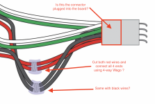
It appears you connect the two red wires (and also the two black wires) leading into the connector. Is that correct? If so, what does that actually do? I told you I'm not an electrician!

Also, if that is indeed what I need to do, can I just cut the two red wires and connect them with a 4-way Wago connector? I know the preferred connection is soldering but I rarely have good results soldering.
Screen Shot 2022-07-02 at 9.02.22 AM.png
 
This is correct. You can cut both red and black wires and tie each one, respectively, together. The board gets its power through the red and black conductors. The Intellichlor is also powered through the red and black. The way it is currently set up, all of the current that the Intellichlor draws, comes in on one red conductor, passes through the connector and a trace on the PCB, and back out through the other side of the connector, out to the Intellichlor. This connection also draws a little bit of power for the control power for the IpH board.

When you tie all the reds together, this creates a junction where the board can pull the little amount of power that it needs, and the Intellichlor can get the higher current power that it uses, without having to drag that current through the connector and the traces on the board. So the only current going through the connector is that which the board needs to run.

The consensus at the moment is that the connector is not designed for the current draw of the Intellichlor, or with age, it corrodes and increases the resistance through the connector, thus causing the failure.

--Jeff
 
  • Like
Reactions: Dirk
Sorry, I didn't answer the rest of your questions.

Yes, you can connect them all with a 4 way Wago connector, a wire nut, or any other suitable device to tie all 4 connectors together.

Soldering is preferred by many but as you saw in my thread, I prefer the ability to remove the connector if necessary. Why? I have no clue. Just my preference.

--Jeff
 
  • Like
Reactions: Dirk
Remember Water and Electricity follow the path of least resistance! This would be where you tie both wires together.
If you are not using Wago for the white and green then i see no use for using wago on the red and black. Either solder or tie together.or Wago al 4.
 
  • Like
Reactions: Turbo1Ton
Remember Water and Electricity follow the path of least resistance! This would be where you tie both wires together.
If you are not using Wago for the white and green then i see no use for using wago on the red and black. Either solder or tie together.or Wago al 4.
Ok, the water analogy helps. I kind of understand how power is being sent from the ET panel through the IpH board and on to the IC40. But, I was having trouble understanding how the correct amount of electricity would be sent through the now spliced wires and the board. IOW, how does the board get the proper amount of power?

As for the Wago connectors - Why would I be cutting the white and green wires? I thought "Fix #1" was just connecting the red wires together and then connecting the black wires together separately.
 
  • Like
Reactions: Flying Tivo
As @Turbo1Ton mentioned Wagos are for the ease of being able to do/undo the connections. What is the need to just do the red/black if you are still attached to the connector with the Green/white? Dont get me wrong, it will work with just red/black.
how does the board get the proper amount of power?
It just gets what the board demands, no more no less. Just like drinking out of a hose, you dont drink it all, right?
 
As @Turbo1Ton mentioned Wagos are for the ease of being able to do/undo the connections. What is the need to just do the red/black if you are still attached to the connector with the Green/white? Dont get me wrong, it will work with just red/black.

You don't need to break the white/green wires. They must go through the board. No need to touch them.

What you are doing with the red and black wires (I don't believe the black is really necessary as that is the 0V reference for the 24V power, but it won't hurt to do it) is you are creating a hub if you will, for the power to flow through. Instead of that hub being on the IpH board, it is now outside of the board and is not funneling that higher current through the connector.

--Jeff
 
I did not mean to cut them, just to bridge them for easy connect/disc.
Thanks for clarifying.

As long as the connector isn't burned, the board connector could be used for easy disconnect of everything.

I personally wouldn't touch the white/green wires. If my connector hadn't burned, I would have only done the red wire and called it good. That is the current carrying leg of this thing.

@bertschb - Brian, I hope we haven't gone too far off and made things more confusing.

--Jeff
 

Enjoying this content?

Support TFP with a donation.

Give Support
If my connector hadn't burned, I would have only done the red wire and called it good. That is the current carrying leg of this thing.

@bertschb - Brian, I hope we haven't gone too far off and made things more confusing.

--Jeff
Thanks Jeff

Th only question I have is with the black wires. If the red wires carry the current and that is what is causing the overheating, why are we messing with the black wires as shown in Fix #1? Any thoughts @Dirk ?
 
The only reason I can think of is because the red and black together make up the power supply circuit. The black wire is the reference 0V for the 24V circuit. There realistically shouldn't be any current through the black wires, since it is DC voltage, but it won't hurt to break them and then you can be sure they won't be an issue.

I don't recall seeing one of the black wire pins on the connector being burned, other than from the red wire pin. Mine was only the red wire pins.

--Jeff
 
I stand corrected. FlyingTivo has a burned black wire pin in his IpH. I just didn't recall that until this morning when I went to this thread to post my pictures... IntelliPH board / connector fried pictures log

So that being the case, I would cut and splice together both the black and red wires.

Sorry if I led you astray.

--Jeff
 
  • Like
Reactions: Dirk
Geez, ya gotta get up pretty early on a Sunday to get your 2¢ in!! But it sounds like you all sorted it out. Not sure, exactly, what Felipe was getting at, but no, you don't have to cut the white and green, and you absolutely would't tie them together before the board as you do with the reds and blacks. I don't think that's what he meant, so I'm just clarifying. The two whites must stay separate, and each connect to the board. Same with the greens. The easiest way to ensure they all do that correctly is to leave them alone.

And Jeff was, at first, confusing voltage and current. Yes, the red has the 24V relative to ground, and the black would be 0V, relative to ground, because the black is the ground. But they are both carrying the same amount of current, and are both subject to burn. As he points out, we sometimes see the red pins burn, other times the black ones. They both need to be joined, just as you did.

My guess is, the pins are of sub-quality metal. All four (two reds, two blacks) can potentially start to corrode over time, but they wouldn't do so equally. It's just "luck-o-the-draw." The one that corrodes first, or worst, starts to resist the current first/most, and so starts to heat up the most, and then perhaps that heat exacerbates the corrosion, and then it's sort of exponential after that, until it fries itself. Just a hunch, but that might explain why we most often see just one pin start to go. But it's not always just one, and it's not always the red one...

I suppose the connector's conductors that are carrying the white and green signals could corrode, too. But we've yet to see any get so bad that the COM signal is interrupted. Which is why my guess is that it is a combination of the poor quality metal, some corrosive accelerant (like moist or humid climate? or muriatic or chlorine fumes (salty air), etc), along with too much current that combine to cause the problem. The white and green COM path doesn't have the excessive current component of the perfect storm, so maybe that's why we haven't seen them lose contact. They may be corroding, but they're not burning.

I wrote in Jeff's thread about waiting until after the warranty to do this, and also that the warranty is likely one year, not 60 days, but geez, I was trying to sleep in a little and didn't get that post off soon enough! No worries, I'm sure you'll be fine.
 
Thanks for the feedback @Dirk

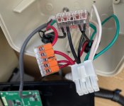
I wish my soldering skills were better because I think hard-wiring directly to the board is a better long term solution. But, the "Wago Fix" may be the next best thing and it's much faster. The only issue I had is the wires in my box were juuuuust barely long enough if you use the Wago connectors. I actually had to reposition the wires in the Wago connectors after I took the picture above to gain just a teeny bit more length so I could get the panel back on the box. That's the only part of this pre-emptive fix that makes me a little nervous. The wires are a little more snug than I'd like. I can always fix my fix by buying a new control box later if for some reason my snug wires cause a poor connection at the connector and ends up melting it anyway.
To gain additional length without soldering you could use wago‘s to connect a jumper wire Instead of the wago itself acting as the jumper. You’d use more wago connectors but would solve for the length issue. Looks like you could also get away with connectors with less ports that way as well.
 
Which is why I drew the diagrams the way I did. By shaving the insulation (instead of cutting) and wrapping the exposed wires with smaller wire, then soldering all that, and then covering it with an insulator (caulk or epoxy or hot glue, whatever), you'd have gotten a great electrical connection and not compromised the wire or the fit, without any possibility of corrosion getting into the mix in the future.

I didn't know all that when I did mine, so I had to extend one set of wires with four short wires, but I still soldered all those in. You could still do that, at some point, if you wanted to. Or extend them with wire and Wacos. But as I wrote elsewhere, each Waco is introducing more unsoldered mechanical contact points, which are what causes the problem in the first place. Hopefully the Waco conductors are of better quality, but they are still mechanical connections. Just sayin'...
 
I checked on the IntellipH warranty and it falls under the TradeGrade warranty (Pool Product Warranty Information). Meaning that if it was purchased online it is only a 60 day warranty. I don't know where Brian purchased his, so his might have had a 1 year warranty, if purchased from a brick and mortar store. If so, sorry about any confusion on that. It is worth noting that we seldom see these failures within 1 year, when running an IC40. The guys running IC60's are another story. I think they are failing within 6 months.

--Jeff
 
  • Like
Reactions: Dirk

Enjoying this content?

Support TFP with a donation.

Give Support
Thread Status
Hello , This thread has been inactive for over 60 days. New postings here are unlikely to be seen or responded to by other members. For better visibility, consider Starting A New Thread.