Installed a New Pump Problem

kkrause32081

Member
Jul 27, 2023
10
Ponte Vedra, FL
Hi,
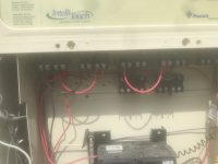
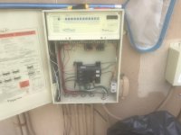
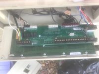
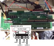
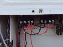
I replaced my dead Pentair Max E Pro pool pump with a 3 HP Black and Decker VS pump. I have an a Intellitouch i7 +3 automation system that connects to an App using screen logic.. I replaced the B&D control panel with the automation adapter that can be used for the B&D pump. When I went to connect the automation cable from the pump to the board, I found a rats nest of cables and could make sense of how to make the connections. I viewed several Youtube videos with folks connecting VSPs to automation boards but never with the i7+3.

I used the same electric connections from the old pump on the new B&D.

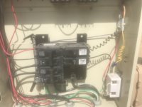
When I try to fire up the pump (turn the breakers on), it is not getting power. The App will not fire up the pump either. The breakers (in the automation box and the main house panel) are not tripping. My uneducated guess is that the pump is not getting power due to the panel not being connected to the pump. Does this seem like a plausible explanation?

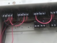
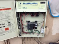
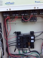
Can anyone give me some ideas on trobleshooting this issue or is anyone an expert on Intellitouch systems? I took lots of picture of the the low volage side and high voltage side if that helps.


.
 
The automation adapter triggers different speed using high voltage relays.

How many unused high voltage relays did you have?

How did you wire the automation adapter to the Intellitouch relays.

Did you move the pump power from the LOAD side of the filter/pump relay to the LINE side to be continuously powered?

Show us pics of the wiring and what you did.
 
Thank you for responding. I didn't change any of the wiring on the automation board. I was operating under the assumption (likely very wrong) that since the old pump was wired "properly" that once I switched the power lines to the new pump the new pump would be able to be powered on without the automation connected. I also did not remove an automation cable from the old pump so that has me puzzled as well... I have not attached the adapter to the automation board as I am confused. Here are the pics of the high voltage side. Thank you for your help.
 

Attachments

  • IMG_1830.jpg
    IMG_1830.jpg
    242.3 KB · Views: 6
  • IMG_1831.jpg
    IMG_1831.jpg
    200.4 KB · Views: 6
Can you post a clear pic of the panel showing the CB and relays so we can see how the wires run from the bottom of the panel?
 
Can you post a clear pic of the panel showing the CB and relays so we can see how the wires run from the bottom of the panel?
Hope these are clearer. I am getting power at the breakers according to my voltage detector. It appears to me from looking at the third picture the relays are connected to the control board with the accordion black wires that are terminated on the board with the purple connectors that connect on the pins for filter pump and AUX 1-6 shown on the second picture.
 

Attachments

  • IMG_1836.jpg
    IMG_1836.jpg
    58.2 KB · Views: 9
  • IMG_1837.jpg
    IMG_1837.jpg
    63.3 KB · Views: 9
  • IMG_1838.jpg
    IMG_1838.jpg
    43.5 KB · Views: 9
Those pictures continue to be cloudy and too small to see the necessary wiring details.

Do you have a multimeter and know how to use it?

Check the voltage on the LOAD screws of the filter/pump relay when the pump is ON and OFF.
 
Sorry for the back and forth. I used a different device for these pictures. After looking at things closer here is the extent of my present knowledge. 1) There is juice flowing to the beakers when I throw the breakers on. I do not have a voltage meter but I have a voltage detector. 2) when the breakers are thrown, the pump does not acknowledge that it is seeing power at all as there are no illuminated lights on its control panel and pushing the various buttons does nothing 3) There are connections from the top of the power relay on the high voltage side of the board and the go through a panel and end up connecting via pins to the various functions on the board that I tried to show that in the first picture.
 

Attachments

  • controller board.jpg
    controller board.jpg
    449 KB · Views: 11
  • IMG_0760.JPG
    IMG_0760.JPG
    355.9 KB · Views: 11
Your filter/pump relay may have failed.

It will take a multimeter to test it.

You have at least two unused relays you can swap for the filter/pump relay.

A voltage detector will not tell you if the voltage is adequate. It is simply a safety device and not a diagnostic device.
 
Your filter/pump relay may have failed.

It will take a multimeter to test it.

You have at least two unused relays you can swap for the filter/pump relay.

A voltage detector will not tell you if the voltage is adequate. It is simply a safety device and not a diagnostic device.
An update on my current situation. I had a local pool maintenance and repair guy stop by and he changed the wiring so that the pump always has power and it is now running. I plan on running the pump at various speeds continuously, I'd like my heat exchanger and salt cell to operate during specified hours when I know the flow rate will be sufficient for use. When I asked the pool guy yesterday, he wasn't much help. It seems that pool store techs and pool guys are use to dealing with a different mfr tying into automation, they are unable to figure it out. So is there any way to run the red wire from my adapter to a relay(s) that will activate the heat exchanger and salt cell in my App on a schedule I set in the App? Pics of the wiring after yesterday's rewiring attached. Thanks in advance for any help !
 

Attachments

  • IMG_0775.JPG
    IMG_0775.JPG
    419 KB · Views: 4
  • IMG_0773.JPG
    IMG_0773.JPG
    334.7 KB · Views: 4
So is there any way to run the red wire from my adapter to a relay(s) that will activate the heat exchanger and salt cell in my App on a schedule I set in the App?

What is an adapter?

Can you identify the wires for your salt cell power and heater power?
 

Enjoying this content?

Support TFP with a donation.

Give Support
An update on my current situation. I had a local pool maintenance and repair guy stop by and he changed the wiring so that the pump always has power and it is now running. I plan on running the pump at various speeds continuously, I'd like my heat exchanger and salt cell to operate during specified hours when I know the flow rate will be sufficient for use. When I asked the pool guy yesterday, he wasn't much help. It seems that pool store techs and pool guys are use to dealing with a different mfr tying into automation, they are unable to figure it out. So is there any way to run the red wire from my adapter to a relay(s) that will activate the heat exchanger and salt cell in my App on a schedule I set in the App? Pics of the wiring after yesterday's rewiring attached. Thanks in advance for any help !
The automation adapter will control the pump only. The SWG can be set in the Intellitouch or with just a relay. Heat exchanger? Pool heater? Heat pump? Showing a small portion of the wiring doesn't provide enough information to be of much help. Where is it going? What equipment? Etc.
 
Thread Status
Hello , This thread has been inactive for over 60 days. New postings here are unlikely to be seen or responded to by other members. For better visibility, consider Starting A New Thread.