IC40 Lights out, with red system error light on IntellipH

3rdcoaster

0
Silver Supporter
Apr 28, 2018
28
Houston TX
My IC40 start-up was in fall 2017, and intellipH was added summer 2020.

Both stopped working recently. IntellipH control box has power, but red error light is on, and the IntellipH message panel says the the salt cell is not on. Manual acid injection is not allowed. All IC40 lights are off. I see no Ca build up on the plates (I acid-cleaned in the summer). There doesn't seem to be a fuse in my IntelliChlor power center, and I wonder is that is unneeded for the power center sold for installation with the Easytouch, which has the circuit breakers.

In 2019 (no IntellipH), the IntelliChlor stopped making Cl, and I had a warranty call which diagnosed a flow sensor issue, so that was replaced.

In past years my system has run under 5K active hours (hr/day*days*percent on), but I'm now beyond the 3 year new pool warranty. Since my pool is small, I run the Intellichlor in the 10-40% range, highest at peak of summer. Some older threads indicate that all lights out is unlikely to be a flow sensor (I can't recall and my notes don't show what the lights were doing in 2019).

I'd welcome any assessments and suggestions for troubleshooting. Does the fact that the IntellipH is on mean that the intellichlor is seeing normal power, and the problem is definitely inside the Intellichlor? Worth replacing the flow sensor, just to see?
Ed
 
Last edited:
3,

I believe that the ipH has a history of having bus lines on the internal board burning open causing the power to be removed from the IC40.

I would remove the IC40's cable from the ipH and connect it to the Automation and see of the IC40 then gets power.

Let's see what @Dirk has to say, as he is more up on the ipH operation than I am..

Thanks,

Jim R.
 
Jim: I would remove the IC40's cable from the ipH and connect it to the Automation and see of the IC40 then gets power.

This helped: IntelliChlor is fine, when driven directly from the power center. Also. the IpH is fine, driven from power center. So PS and IntelliChlor are fine, and there's a problem getting power out of the IpH control box, although it is able to talk to the IpH pump. I've started to look at the older threads on the further reading page. I didn't yet see the same issue described...making progress. Thanks.
Ed
 
Last edited:
Before DIYing any solution, I would contact Pentair and push for a warranty replacement. It sounds like it could be the power-overload problem. Pentair is well aware of the issue, and maybe they can help. I'll PM you some details.
 
Thanks for everyone's feedback, as i am coming up to speed I see this is a "known issue" with intellipH. I am out of warranty and got a lot of repairs under warranty, this one is on me (and more to come!!).

I opened the intellipH control box (3 screws) and it seems that I have a recurrence of the "black pin burnout". There's an 8 pin connector soldered to the IpH controller board, and the 2 slots with the black wire connections from the power center and to the salt cell are burned, as shown here: Pentair IntelliPh Circuit?wiring supply issues.

I have a hint that it this connection is the only this issue: after the salt cell ran for several hours without a problem. I disconnected it and reconnected via the IpH (now fully cooled down). I restarted and the salt cell ran for a few minutes, then shut down. The IpH also operated correctly without an error light until the salt cell shut off. When I restarted moments later the salt cell began its start up routine for a second, then shut down. Reconnected directly to the power center, it runs fine.

Welcome any recs or warnings. The connectors are only a few dollars but require resoldering to the board, which could also be damaged (though no sign of that yet). I do not see the intellipH circuit board sold as a separate item online so far. New boxes are about $225 and up. Much less than a new salt cell, which is now up to over $800.
thanks all!
Ed
 
I wouldn't fix the connector, or replace the board. It'll just happen again.

If it was mine, and I had exhausted all threats to Pentair and throwing a hissy fit, I would proceed to fix it myself. I think there was a guy here who figured out how to fix/replace the connector. I wouldn't bother. The connector on the board has pins that solder onto the board. I would cut off that connector and leave as much of the pins as possible. Then I'd cut the connector off the wire bundle, and then solder the wires onto the pins. (Making sure I first observed and recorded which wires go where, of course!) If you know how, I'd slide some heat shrink tubing on the wires first, solder them to the board, let them cool, then slide the heat shrink tubing back over the solder joint and the pins, and heat it into place. That would ensure a good insulated connection.

This solves two issues: it removes the faulty connector from the equation, so it can't melt again. And that also negates the possibility that the connector can corrode and cause a different, but similar, connection issue.

If at some point in the future you need to replace that little circuit board, then just repeat the process (cutting out the connector of the new board and soldering the old wires to the new board)...

@Jimrahbe, I gave the "call Pentair" pep talk to 3rdcoaster in a PM. They rejected him. I even suggested to call back, get a different guy, and see if he'd bite. They should be fixing his in or out of warranty. Anywho, more to the point, this was an IC40 this time. I think all the other occurrences have been with the 60. Pentair should recall every last one of 'em...
 
Last edited by a moderator:
All thanks for your advice and enthusiasm.
I am attaching some close-ups of the burnout of one pin within the nylon AMP type power supply connector, for the record. AMP is made by TE.com. I can learn if this is rated for an outdoor/damp application with this current range. Seems like this black connection from the power center to board had a poor contact or got corroded, causing increased resistance and burnout. The modular connector clipped and soldered to the board has 8 pins, and the lower row of pins are pretty short. This might not be the right connector for the application, bu it doesn't seem like a novice task to take it apart and resolder without a connector. Since my unit is only 6 months old, this does seem like a design concern. We'll see if TE has a suggestion for a more robust connection, others welcome. Ed
IMG_4745.jpgIMG_4746.jpgIMG_4747.jpgIMG_4748.jpgIMG_4749.jpgIMG_4744.jpg
 
Last edited:

Enjoying this content?

Support TFP with a donation.

Give Support
but it doesn't seem like a novice task to take it apart and resolder without a connector
I've done it dozens of times... in my mind! 🤪 
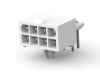
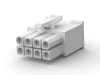
I wonder if the right attachment on a Dremel could slice away the plastic just so and leave the eight pins exposed.

How many wires are there? Is it four, or eight? Looks like the top row, at least, is involved, which is good.

The reasons I suggested soldering directly to the pins, instead of trying to replace the connectors:

- unsoldering from a circuit board is tricky. I've done it, but it requires a special tool. It takes significantly more exposure to heat to unsolder than to solder, and I'd be worried about damaging the board, especially since you'd have to apply that heat eight times. You have to heat one joint at a time, suck off the hot solder completely, and repeat seven more times. Who knows what would happen to the board traces after all that.

- The other end might be tricky, too, and require some sort of crimping tool (just guessing).

- Even if you were successful with all that, you're still stuck with the same problem, poised for it to repeat itself.

- Soldering to the pins will be a very solid connection, and not subject to future corrosion. You'd have to be quick about it, or else you risk melting the solder holding the pin to the board. The trick is to use a soldering iron of sufficient wattage, but not too much wattage. And apply a heat sink to the pin, to draw off some of the heat. I use a surgical clamp for that.

I wouldn't call it a simple DIY task, but I'd give it a go myself before plunking down for a new board.
 
Still stewing on this. There's possibly a simpler fix for this. Not pretty, but easier. And that is to cut the black wire off the male connector and then reconnect the male end to the board. The other seven pins appear to be fine, and capable of handling the current they are carrying. Then solder the black wire to the exposed pin. Basically just bypassing the connector for just the one problem wire. If there is a second heavier gauge wire on the top row, I'd be inclined to do that one, too.

IMG_4748.jpg
 
Nice. If it works, I will take full credit. If it blows up, uh, I was never here... 😈

Black wire bypass update

I have a nearby computer repair store I have used for other issues, and brought the disassembled ipH controller box to them and described the proposed bypass procedure. They said they were a bit worried about melting the nylon connector too much, but gave it a go. Pics show the result.

IMG_4755--ipH repair2.jpgIMG_4755--ipH repair1.jpg

I reconnected everything, it started up fine and has worked without a problem for 4 days--I'll try to report back again in a year. They did some extra steps, adding a tiny bit of (red) shrink wrap at the end of the pin near where it contacts the board, tinning the braided wire before soldering onto the pin, and, at my request, shrink wrapping (blue) over the cut end of the black wire as it entered below the connector. Zip tied for extra stability, it is very strong.

Does anyone understand why AMP connector for the black wire from the power supply to the board would be susceptible to this -- does it carry more current? Or is it that there was an issue with the crimping of that pin of the connector? But this seems same as previous examples described by others...

thanks for the help!
Ed
 
The black wire is probably the “hot” wire. The other wires are neutral, ground, or data lines. That pin probably has high resistance creating heat on the hot line.
 
We think the black wire carries the current for the SWG (among other things), though I'm not sure it's the hot wire. In DC wiring, red is usually the hot wire (which only matters for the point I make below). Someone here had heard from Pentair that they were going to address this problem by discouraging (somehow?) the use of the IC60 with the IntellipH. That led us to believe the lesser amperage requirement of the IC40 and IC20 is not sufficient to melt the connection. We now know that's not true in all situations. If it is in fact the current draw of the IC causing the problem, then that current is likely running through the black wire (but maybe not only that one wire, read on).

For a while, I think you should check on that connection periodically. I think it's possible that another wire could fail. It follows that if X amount of current was traveling through that black wire, then all or some of that current is traveling back out through one of the others. It's also possible that the current splits up and travels out through more than one wire, but I think its possible that most of it is traveling out through just one. I suspect the red one, for two reasons. If you look very closely at the pic that I modified, it looks a bit like the pin just to the right of the fried one has similar tinging on it. It's very vague, and maybe not there, but that is the red wire pin. If I was engineering this thing, and was coming up with the color scheme, I would run primary power through the red and black wires. Black would be common and/or negative, and red would be the positive DC wire to the SWG. In other Pentair four-wire connections, the red and black are power, and the other two are signal wires, so that might be Pentair's color scheme. So...

It's possible that the black wire (the common wire) had the most amps running through it, and the red wire had the second most. The black wire's pin connections acted a bit like a fuse. It burned out first (like a fuse would), because it had the most amps running through it. But now that you've bypassed the pins, you've eliminated that "fuse." Which might subject the next in line to be the next fuse. This is all very obscure, and maybe not likely. But it's worth keeping an eye on. Obviously that connector is inadequate for the current running through it. It's not a given that only the black wire is running too much current.

Anywho... thanks for pursuing this. You may have proven the workaround for others. We'll look forward to your future reports. Whoever did that work for you did a first rate job. And you've now provided the model for the fix.
 
Last edited:
  • Like
Reactions: 3rdcoaster
Dirk: more or less my thoughts. Would add: burn may not be related to the current per se, but due to corrosion of the wire pressure contacts in the connector, which just isnt up to the outdoor location and frequent on/off cycles. Corrosion causes resistance causes heat at the rated current. We'll see. Ed
 
  • Like
Reactions: Dirk
Dirk: more or less my thoughts. Would add: burn may not be related to the current per se, but due to corrosion of the wire pressure contacts in the connector, which just isnt up to the outdoor location and frequent on/off cycles. Corrosion causes resistance causes heat at the rated current. We'll see. Ed
That is exactly right, and certainly must be a factor. I would say it's a factor in why yours burned with only an IC40 connected, where the problems we've seen here, up until yours, have been with the IC60. But it's always been that black wire, which is why we think we know that wire is carrying the most current.

When wiring with aluminum wire, you're supposed to use a special antioxidant paste to combat the oxidation that can interrupt current flow and cause overheating. I wonder it some sort of similar compound shoved into the compartments of that connector could help? That's not any sort of specific advice, nor would I know what compound to use. Just wondering out loud.

That's why I originally suggested soldering all the wires to their pins, to eliminate the potential problem for all the current paths. Soldering takes corrosion out of the equation...

No matter, you know what to look for, and how to fix it if you have any more issues.
 

Enjoying this content?

Support TFP with a donation.

Give Support
Thread Status
Hello , This thread has been inactive for over 60 days. New postings here are unlikely to be seen or responded to by other members. For better visibility, consider Starting A New Thread.