I need help understanding how the EasyTouch8 is configured/meant to work. I figured this made sense to be in a new thread, so notifying @GDN or @bdavis466, since this is in relation to a post/diagram from them.
Goal: To provide load to an available AUX relay ONLY when the mail pump is on.
Purpose: I'm installing a DIY automated liquid chlorinator. I do not want to take a chance at my schedules not working properly. Thus, I want to chain the power to the AUX relay so that I literally cannot turn it on unless the main pump is running. This will ensure the chlorine pump will never be on unless the main pump is on. And even then, I will put the AUX relay on a schedule to only come one at certain times when the main pump is on.
Problem:
The gist seems really simple. See this post for the basic diagram I'm trying to follow. Unfortunately, in looking at my wiring, I'm not seeing it configured as I would expect.
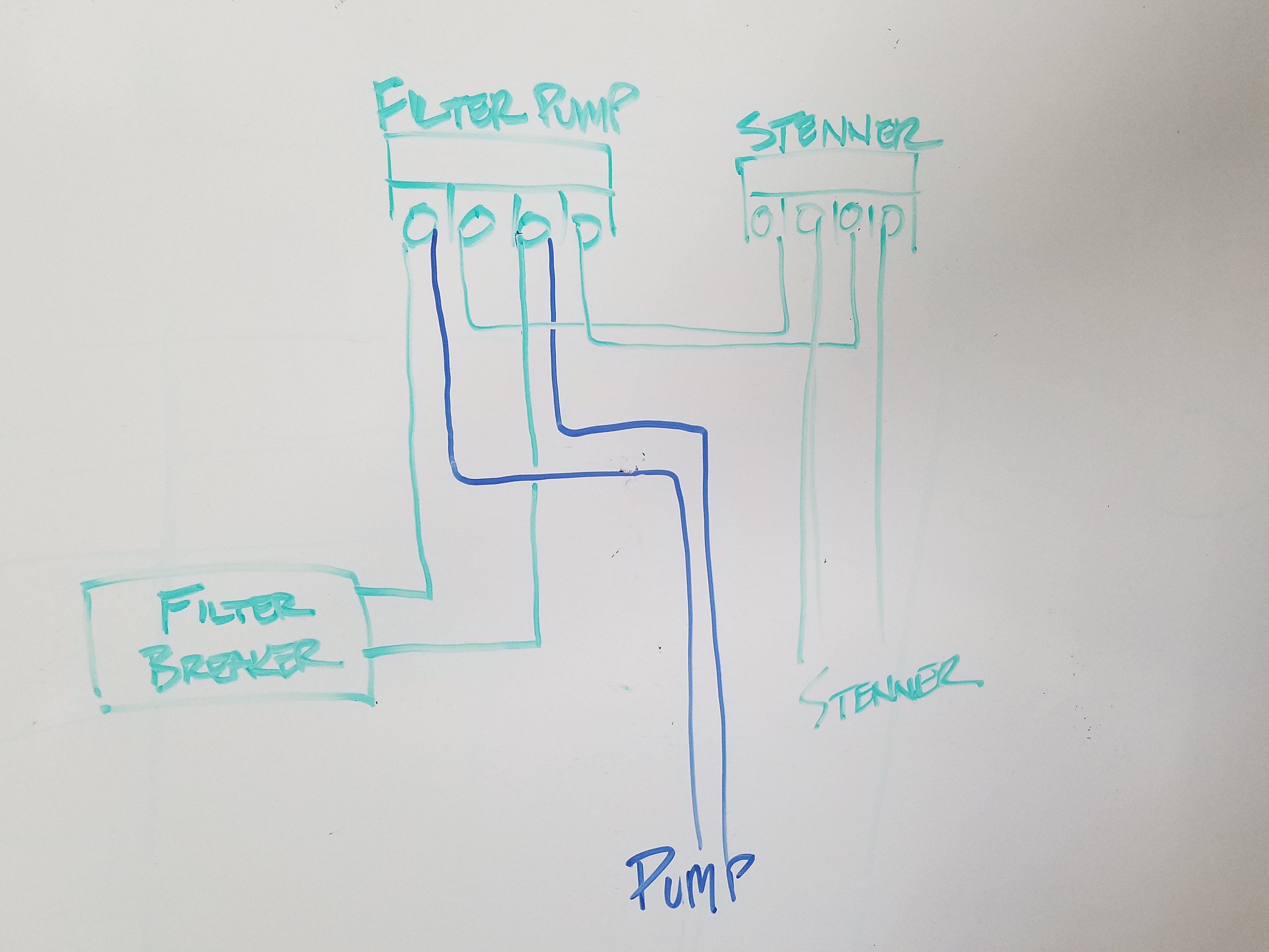
In the main panel diagram (see below), it looks like the first relay is "Filter Pump." I would expect this to be powered by a breaker, and I would expect the "load" terminals to become hot when the "Filter Pump" is turned on.

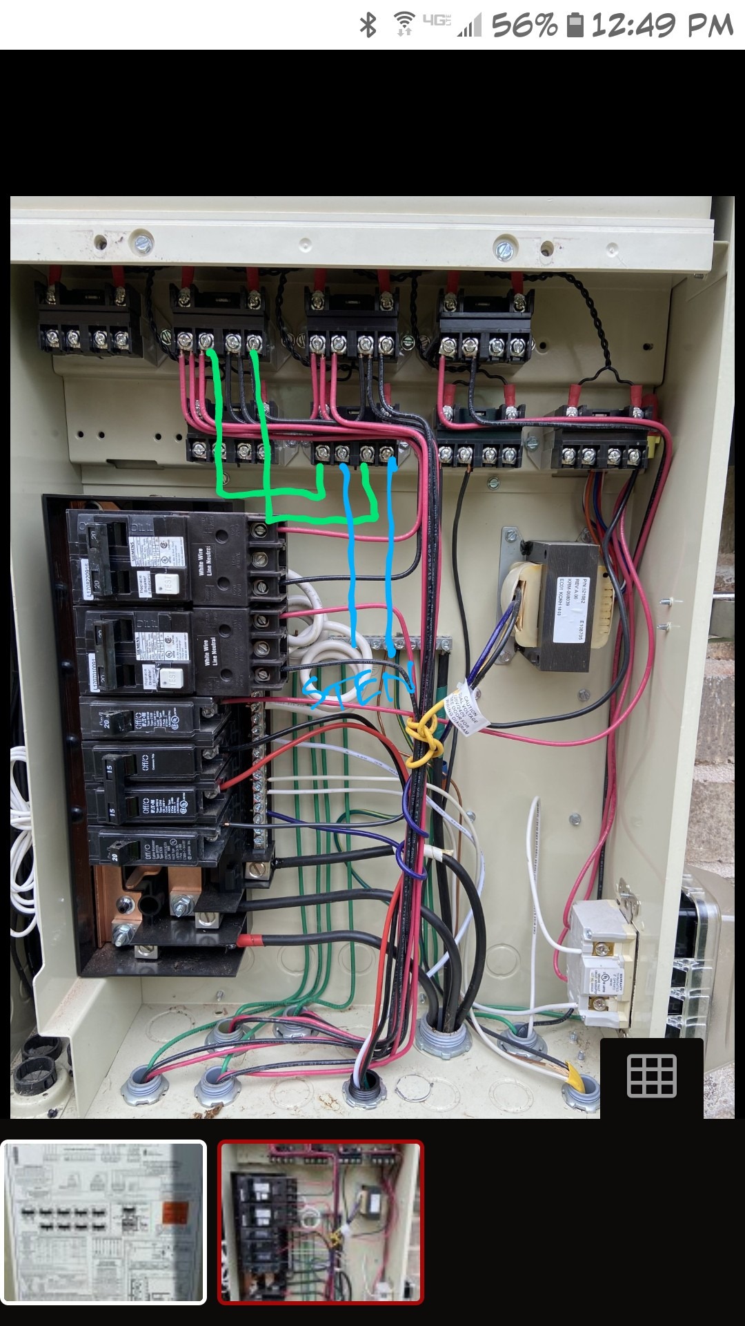
Below is a picture of how it's actually configured. The second 220 breaker is going to the pump. There are no lines going into the "Filter Pump" relay. However, my system works, so I must not understand the wiring/diagram. (By "my system works," I mean that when I push the "Filter Pump" button on the ET8 control panel, it turns my filter on. So, clearly, something is hooked up and controlling this appropriately. Just in case, I turned the pump on and then tested the Load side of the Filter Pump relay, but I got no power reading. Then, I though about feeding power to the Line side of the Filter Pump relay, but I'm not sure that's a good idea, because I don't know if that would overload the pump (would it send more power to the pump in this case?).

If anyone has pics they could share of how their ET4 or ET8 is hooked up, that would be very helpful.
And if you have any insight into how the ET4 or ET8 wiring works, especially that Filter Pump relay, let me know.
Any help is greatly appreciated!
Goal: To provide load to an available AUX relay ONLY when the mail pump is on.
Purpose: I'm installing a DIY automated liquid chlorinator. I do not want to take a chance at my schedules not working properly. Thus, I want to chain the power to the AUX relay so that I literally cannot turn it on unless the main pump is running. This will ensure the chlorine pump will never be on unless the main pump is on. And even then, I will put the AUX relay on a schedule to only come one at certain times when the main pump is on.
Problem:
The gist seems really simple. See this post for the basic diagram I'm trying to follow. Unfortunately, in looking at my wiring, I'm not seeing it configured as I would expect.
In the main panel diagram (see below), it looks like the first relay is "Filter Pump." I would expect this to be powered by a breaker, and I would expect the "load" terminals to become hot when the "Filter Pump" is turned on.
Below is a picture of how it's actually configured. The second 220 breaker is going to the pump. There are no lines going into the "Filter Pump" relay. However, my system works, so I must not understand the wiring/diagram. (By "my system works," I mean that when I push the "Filter Pump" button on the ET8 control panel, it turns my filter on. So, clearly, something is hooked up and controlling this appropriately. Just in case, I turned the pump on and then tested the Load side of the Filter Pump relay, but I got no power reading. Then, I though about feeding power to the Line side of the Filter Pump relay, but I'm not sure that's a good idea, because I don't know if that would overload the pump (would it send more power to the pump in this case?).
If anyone has pics they could share of how their ET4 or ET8 is hooked up, that would be very helpful.
And if you have any insight into how the ET4 or ET8 wiring works, especially that Filter Pump relay, let me know.
Any help is greatly appreciated!