EasyTouch 8 (ET8, or even ET4) Wiring Help

Jul 8, 2018
108
Austin, TX
I need help understanding how the EasyTouch8 is configured/meant to work. I figured this made sense to be in a new thread, so notifying @GDN or @bdavis466, since this is in relation to a post/diagram from them.

Goal: To provide load to an available AUX relay ONLY when the mail pump is on.

Purpose: I'm installing a DIY automated liquid chlorinator. I do not want to take a chance at my schedules not working properly. Thus, I want to chain the power to the AUX relay so that I literally cannot turn it on unless the main pump is running. This will ensure the chlorine pump will never be on unless the main pump is on. And even then, I will put the AUX relay on a schedule to only come one at certain times when the main pump is on.

Problem:
The gist seems really simple. See this post for the basic diagram I'm trying to follow. Unfortunately, in looking at my wiring, I'm not seeing it configured as I would expect.

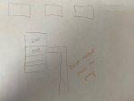
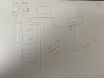
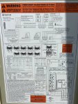
In the main panel diagram (see below), it looks like the first relay is "Filter Pump." I would expect this to be powered by a breaker, and I would expect the "load" terminals to become hot when the "Filter Pump" is turned on.
1590261390150.jpeg

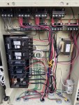
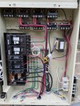
Below is a picture of how it's actually configured. The second 220 breaker is going to the pump. There are no lines going into the "Filter Pump" relay. However, my system works, so I must not understand the wiring/diagram. (By "my system works," I mean that when I push the "Filter Pump" button on the ET8 control panel, it turns my filter on. So, clearly, something is hooked up and controlling this appropriately. Just in case, I turned the pump on and then tested the Load side of the Filter Pump relay, but I got no power reading. Then, I though about feeding power to the Line side of the Filter Pump relay, but I'm not sure that's a good idea, because I don't know if that would overload the pump (would it send more power to the pump in this case?).
IMG_0737.jpeg

If anyone has pics they could share of how their ET4 or ET8 is hooked up, that would be very helpful.

And if you have any insight into how the ET4 or ET8 wiring works, especially that Filter Pump relay, let me know.

Any help is greatly appreciated!
 
What does the top 220v feed? Another VS pump?

It looks like that relay is wired how the Filter pump relay should have been. If it is the Filter relay then:


OK, I think I get it now. The first 220 break powers (1) Water feature pump (not VS); (2) Heater; (3) Spa Air Blower. That's why there are so many "Line" wires--all feeding off the same breaker.

The second 220 break is the main pool pump, which is VS. It's wired directly.

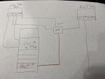
So, if I understand correctly, I could go from this:
Current.jpg

TO this:
Modified.jpg

And that would keep continuous power to the main pool pump still, but the power to the "Stenner" relay would only power on when Filter Pump relay is on (so, Filter Pump Load to Stenner Line; Stenner Load to Stenner pump). Correct?
 
No it doesn't matter but I think it simplifies things having it on the same breaker. That way if the breaker was the trip nothing on that circuit would work. Every one of these panels I've ever wired up have always had the pump heater and swg on the same breaker without issue
 
No it doesn't matter but I think it simplifies things having it on the same breaker. That way if the breaker was the trip nothing on that circuit would work. Every one of these panels I've ever wired up have always had the pump heater and swg on the same breaker without issue
Makes sense. I'll try that next.

-------------------------

I got it all hooked up like drawn up. Unfortunately, every time I turn on the AUX 5 relay, the 220 breaker trips. :(

Thankfully, the pump works just fine when only the pump is on, so I can at least keep my pool running.

Any thoughts on what would be causing the breaker to trip? The setup is pretty simple.

For the breaker:
  • Top of breaker wired to Filter Pump (FP) relay Line 1 terminal
  • Bottom of breaker wired to FP relay Line 2 terminal.
Relays:
  • FP relay Load 1 terminal to AUX5 relay Line 1 terminal
  • AUX5 relay Load 1 terminal to black wire going out to receptacle.
Wiring of Outdoor Outlet:
  • I'm using 12 gauge wire housed in 1/2" conduit to an outlet mounted on the wall.
  • At the wall, the black and white wires are connected to the Line terminals on the receptacle. Ground wire is connected to receptacle ground.
  • In the ET8, the ground wire is connected to the ground block in the ET8 (green wires).
  • The white wire connected to the neutral block (like other white wires).
  • The black wire is connected to the Load 1 terminal on the AUX 5 relay Load 1 terminal as mentioned above.

What would you recommend for troubleshooting steps? Only thing I can think of is this:
  1. Remove black wire (coming into the ET8 for the outlet) from AUX5 relay. Turn on filter. Turn on AUX5 to see if it trips. If so, maybe it's the AUX5 relay?
    1. Tried this, and breaker did not trip, so AUX5 Line 1 terminal is fine.
  2. Replace black wire. Disconnect receptacle, separate wires at receptacle so they cannot touch. Turn on filter. Turn on AUX5 to see if it trips.
Anything else you would try?
 
Last edited:
Post pics of the way you wired it.

You likely are tripping the GFCI because you split the load on the breaker.
 

Enjoying this content?

Support TFP with a donation.

Give Support
You can’t steal power from one leg on a 240v GFCI breaker without the GFCI seeing it and tripping.

Can the Stenner run on 240V?

That is what Brian drew in post #2.
 
You can’t steal power from one leg on a 240v GFCI breaker without the GFCI seeing it and tripping.

Can the Stenner run on 240V?

That is what Brian drew in post #2.
No unfortunately not. I bought the 110v version, because I didn't have a need to do 220v. :(

I'm sure returning the pump, especially since I've opened it would be costly. I'm hoping there's another way to solve the problem. Otherwise? I might just have to put a 110 breaker in and forget chaining it off the pump. ?
 
Get a 240V SPST relay. Have the 240V relay coil energized by the Pump relay. Have it switch the hot line running from a 120V CB to the AUX5 relay.
 
The neutral wire from the pump needs to connect to the neutral terminal on the GFI breaker, not the neutral bus bar. Its that center screw in the GFI breaker with the sticker that says white wire. If wired correctly the GFI breaker shouldn't trip.
 
Last edited:
Get a 240V SPST relay. Have the 240V relay coil energized by the Pump relay. Have it switch the hot line running from a 120V CB to the AUX5 relay.

That went way over my head, lol. I'm not familiar with SPST relays, though I watched a video on it to try to understand. Didn't quite get it, other than allowing a "switch" to turn power on/off.

Would this use the two Load wires from the Filter Pump relay to provide power to the relay (turning it on), and when it turns on, it then allows a separate 120V breaker to power the AUX5 relay? Is that the point of the relay--to have something close the loop for the 240v breaker, but use a different source of power (the new 120v breaker) to power the AUX relay? And thus, when the power is cut from the 240v breaker, it "turns off" the circuit for the 120v breaker?

Something like this?
IMG_0759.jpg

Doesn't look like a 240V SPST relay is something I can find at a local store is it? Would I have to order it online? I also am not quite sure what to get, nor how I would wire it up once I had it.
 
Try what Brian said in post #14. If it still does not work we will discuss the 240V relay more.
 
The neutral wire from the pump needs to connect to the neutral terminal on the GFI breaker, not the neutral bus bar. Its that center screw in the GFI breaker with the sticker that says white wire. If wired correctly the GFI breaker shouldn't trip.
Try what Brian said in post #14. If it still does not work we will discuss the 240V relay more.

Will do. Thanks to both of you! It's dark now, so I'll try it in the morning and will let you know the results.
 
The neutral wire from the pump needs to connect to the neutral terminal on the GFI breaker, not the neutral bus bar. Its that center screw in the GFI breaker with the sticker that says white wire. If wired correctly the GFI breaker shouldn't trip.
What is that neutral line used for on a 240V CB? I read online it's to complete a 120V circuit, but I don't know exactly the impact. Would that interfere with the pump needing a 240V circuit? I don't quite understand how circuit breakers work, TBH, so, sorry if that's a dumb question.

I also read that using the neutral could cause the breaker to fault b/c it senses a ground fault. Not sure if that's true, and also not sure if I'm applying my reading correctly. I'm just scared of doing something that might mess up the pump, and then I'll be in real trouble. :oops:
 
On the 120v Stenner circuit the current flows back through the neutral line. You have to return the current back through the GFCI CB for it to see it and be happy. It is the way GFCI works.

Both sides of 240V hot lines or 120v hot/neutral lines need to connect to the GFCI CB.
 
On the 120v Stenner circuit the current flows back through the neutral line. You have to return the current back through the GFCI CB for it to see it and be happy. It is the way GFCI works.

Both sides of 240V hot lines or 120v hot/neutral lines need to connect to the GFCI CB.
Gotcha. I read somewhere else someone recommending the SPST or DPST method as well, but I'd rather try moving the neutral wire if it's safe, because it's easier and doesn't require more parts. ? I'll give it a go on the morning. Thanks!
 

Enjoying this content?

Support TFP with a donation.

Give Support
Thread Status
Hello , This thread has been inactive for over 60 days. New postings here are unlikely to be seen or responded to by other members. For better visibility, consider Starting A New Thread.