The bottom left in the back that comes up top and into the filter relay? It's connected to Superflo VS pump.What is that black cable in the back left of the panel connected to the filter/pump relay connected to?
Those thin wires are not to code to be connected to a 20A CB.

Easy Touch 4 question
- Thread starter Cag41873
- Start date
You are using an out of date browser. It may not display this or other websites correctly.
You should upgrade or use an alternative browser.
You should upgrade or use an alternative browser.
I would like to do as you suggested and have the pump set on times to turn on and off from the panel and run the schedule on the actual pump.Cag,
The pump is not being powered by the thin wires.. Your pump is connected to constant AC power from the Breaker..
The thin wires are being used as an external control voltage.. Depending on which thin wires have the 120 Volts AC, tells the pump to run at a set speed. In your case you have two wires, so you can only have two speeds... If you had more relays, you could select more speeds.
Notice the Yellow and White wires on the Pump/Filter relay.. They are connected to the load side of the relay, so the Cell's power center only gets AC power when the relay is closed.. Which would be AUTO, Pool or Spa modes.
If you are happy with what you have, there is no reason to change it.
Thanks,
Jim R.
This is what I want to do.Normally, a VS pump gets constant AC power... In your case, I would wire your SuperFlo to the load side of the Pump/Filter relay. This means that the pump will turn on and off using the EasyTouch. Then you set the pump's internal program using the pump's control head.. You could set the pump to run at one speed or several speeds during the day.
Ahultin
Bronze Supporter
- Aug 19, 2021
- 1,600
- Pool Size
- 17700
- Surface
- Plaster
- Chlorine
- Salt Water Generator
- SWG Type
- Pentair Intellichlor IC-40
Are you using a pool builder? Who wired the easytouch? Have you had final inspection by the county? There are several red flags in the load center I would have corrected prior to warranty service as this looks like an improper install!
1. No gfci breaker on the pump - see https://www.troublefreepool.com/wiki/index.php?title=Electrical_GFCI#:~:text=Pool%20motors%20require%20GFCI%20protection,and%20must%20be%20GFCI%20protected.&ved=2ahUKEwiGoM6_gLaCAxUyPkQIHX07AzIQFnoECBEQBQ&usg=AOvVaw0vimPmnDU-w93-yDxHMMy3
2. Pump breaker is double stabbed
3. White wire used as hot (from gfci to relay 2)
4. Black wire used as neutral ( to gfci outlet , technically ok as it has been taped white but makes troubleshooting down the road a pain)
5. Tiny Low voltage wire running 120v (pump relay, what feeding)
6. Maybe the photo is deceiving but the thhn all looks to be 14g, including the 20 amp pump whip
7. Looks like you have rs-485 hookup to the pump (right side of pump photo), and the antenna but there dont appear to be 3 landed on the board. Rs485 goes from board to swg surge card then there is one set of wire from the surge card to either the pump or the antenna but doesnt appear to be both.
This isnt in the load center but I also noticed that the "backflow" valve being used for the autofill is not of the type allowed/required for San Diego county unincorporated.
Last edited:
- Jul 21, 2013
- 65,306
- Pool Size
- 35000
- Surface
- Plaster
- Chlorine
- Salt Water Generator
- SWG Type
- Pentair Intellichlor IC-60
Note he has another thread here…Are you using a pool builder? Who wired the easytouch? Have you had final inspection by the county? There are several red flags in the load center I would have corrected prior to warranty service as this looks like an improper install!
1. No gfci breaker on the pump - see https://www.troublefreepool.com/wiki/index.php?title=Electrical_GFCI#:~:text=Pool%20motors%20require%20GFCI%20protection,and%20must%20be%20GFCI%20protected.&ved=2ahUKEwiGoM6_gLaCAxUyPkQIHX07AzIQFnoECBEQBQ&usg=AOvVaw0vimPmnDU-w93-yDxHMMy3
2. Pump breaker is double stabbed
3. White wire used as hot (from gfci to relay 2)
4. Black wire used as neutral ( to gfci outlet , technically ok as it has been taped white but makes troubleshooting down the road a pain)
5. Tiny Low voltage wire running 220v (pump relay, what feeding)
Easy Touch 4 question
I am under construction and purchased the easy touch 4 with salt. So the four will be used for pump, salt, lights and bubblers. and still will have plenty of power after those. Is it possible to run some power from that to have a couple electrical outlets out by pool instead of running a whole...
 www.troublefreepool.com
Combined threads -- TFP Mod
Last edited by a moderator:
Ahultin
Bronze Supporter
- Aug 19, 2021
- 1,600
- Pool Size
- 17700
- Surface
- Plaster
- Chlorine
- Salt Water Generator
- SWG Type
- Pentair Intellichlor IC-40
Missed that, I was surprised you hadnt called out the lack of gfci, makes more sense nowNote he has another thread here…

The low voltage hooked up to the comport looks grey and not white. Most likely from the swg. I don’t think the antenna is even hooked up. I would remove the pumps low voltage and run speeds on the back of the pump or place the pump on the load side of FP relay and run a single speed.
For the antenna, the rs485 is running from the antenna to the spot on the board for the antenna, am I missing something else that this needs to be hooked up?The low voltage hooked up to the comport looks grey and not white. Most likely from the swg. I don’t think the antenna is even hooked up. I would remove the pumps low voltage and run speeds on the back of the pump or place the pump on the load side of FP relay and run a single speed.


The antenna is hooked to the comport on the surge card. From previous pictures it didn’t look any of those comports were used.
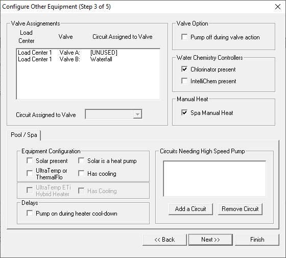
Hi all, thank you for all your input, I had a warranty service call and the outside antenna was bad and replaced and I'm all set up and running now. New question, I installed a valve actuator for my Jandy valve that runs my bubblers on the Baja shelf. It is installed and plugged into the Valve A port on the Easy Touch panel. How do I set it up in the system to turn it on in the Screen Logic app? I assigned Valve A to a Feature but don't know how to turn it on or have it show up in the app to turn on? I signed I to Feature 3 and turned on and it doesn't activate the valve. From what I understand I don't have to use an actual circuit of the four that I have to run the valve so what do I do in the system to turn on the valve in Screen Logic with just using the Valve A port?
Cag,
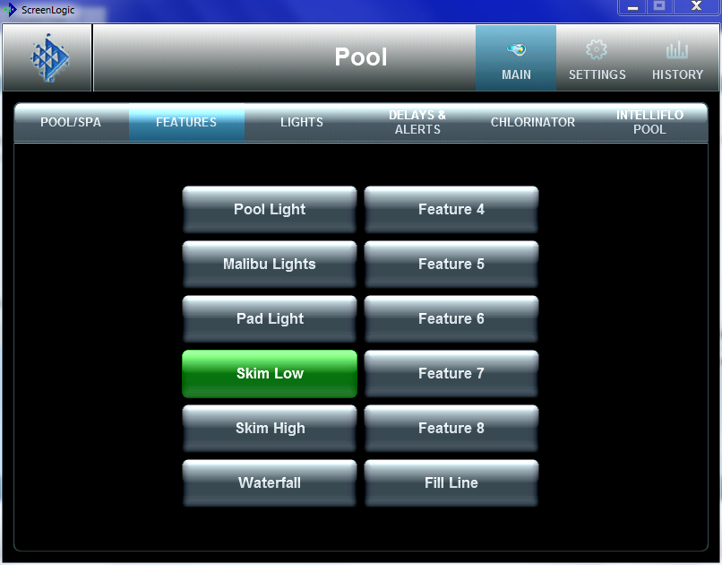
I assigned a Feature circuit called "Waterfall" to Valve B
Then "Waterfall" shows up on my Feature page.
Keep in mind you have to tell ScreenLogic what page you want it to show up.. See "Show on Box.."
Thanks,
Jim R.
I assigned a Feature circuit called "Waterfall" to Valve B
Then "Waterfall" shows up on my Feature page.
Keep in mind you have to tell ScreenLogic what page you want it to show up.. See "Show on Box.."
Thanks,
Jim R.
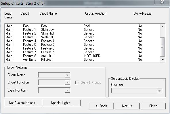
Thank you so much. In picture one and three what software is that? I downloaded the software off Pentair website and I only have what the second photo shows 
- May 3, 2014
- 62,702
- Pool Size
- 6000
- Surface
- Fiberglass
- Chlorine
- Salt Water Generator
- SWG Type
- Pentair Intellichlor IC-40
Thread Status
Hello , This thread has been inactive for over 60 days. New postings here are unlikely to be seen or responded to by other members. For better visibility, consider Starting A New Thread.