- May 3, 2007
- 18,185
- Pool Size
- 20000
- Surface
- Plaster
- Chlorine
- Salt Water Generator
- SWG Type
- Hayward Aqua Rite (T-15)
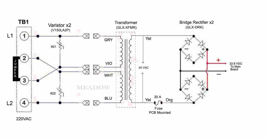
The dc side is the ones with the red and black wires connected. Ac has the orange wires.

so if I test 2 oranges and they have ac current then can we assume rectifier issue?The dc side is the ones with the red and black wires connected. Ac has the orange wires.
right now I am only measuring 7V with the 2 orange wires. This is weired because it should be 24 v.Yes. They connect to the transformer yellow wires via K1. So K1 must be engaged as with the black/red wires.
I did not make sure k1 was on for the orange to orange test. also The leads for the orange wires are so firmly attached to the board I was concerned I would damage the connectors so I measured the ends of the wires and I suppose there could be a break but I did not see one. do I need to go to default menu again to test orange wires? Also will the display be operational to reset K1 if I remove orange to test? Yes definately ACDid you make sure K1 is switched on?
You are measuring ac right?
Take the orange wires off the board and then measure the voltage on the board connectors.
Could it be the transformer even if the yellows read 24 volts?Well I did get those wires off and tested voltage directly from the board pre and post reset. There is an issue with a voltage drop here should be 24 ac but only 7-8 V.
tell me exactly what pictures you would need please.Can you show pictures of everything?
 www.troublefreepool.com


Right! I believe I investigated these through the back door. As I understand it, the orange wires supply 24 AC to the rectifiers and the Red and black bring back 24 dc to the board. Unfortunately my orange wires only supply 7-8V ac to the rectifiers. The fuse was tested but if it was bad I believe there would be 0 volts.There are two bridge rectifiers mounted in the upper right of the case, not on the board, that convert 24V AC to 24V DC.
They look like this...

This thread discussed replacing the rectifiers...
fuse keeps blowing on Hayward swim pure salt water panel.
Hello, May salt water panel recently went dead, no lights, no power, no digital display etc. I replaced the black circular resister as previously in the past believing this was the issue and fix as previously. After swapping out the resister, I reinstalled the circuit board with all the wires...


That is for the Aquarite, not the Prologic.In the diagram above showing the transformers and rectifiers, It suggests that I would see 24 V AC if I put my meter on a Yellow and an Orange as opposed to 2 oranges. Am I reading this wrong?
