Board Repair

That is for the Aquarite, not the Prologic.

The 24 VAC from the yellow wires connects to the board and then that transfers to the orange wires through the 20 amp fuse and the orange wires go to the rectifiers.

If you have 24 VAC on the yellow and not on the orange, then there is a problem with the board.

Send it back for a warranty exchange.
Wish I could but I bought it as a "new" unopened board on ebay and "no returns" that was really dumb on my part and out 500+. Yes I agree there is a board problem and I would like to try to fix or I'm out of luck
 
The top yellow goes through the yellow 20 amp fuse to the top orange.

The bottom yellow probably goes through the small white rectangular fuse to the bottom orange.

Check the voltage from the top orange to the bottom yellow. Should be 24 VAC.

Check the voltage from the top yellow to the lower orange. Should be 24 VAC.

Check the voltage from the top yellow to the top orange. Should be 0 VAC.

Check the voltage from the lower yellow to the lower orange. Should be 0 VAC.

Check from Yellow to yellow. Should be 24 VAC.

Check from orange to orange. Should be 24 VAC.

Check the thermistor (Inrush Current Limiter) resistance with power off. It should be 50 Ohms.

Check the white rectangular fuse next to lower orange and lower yellow.

1702699878092.png
 
Last edited:
I had an older Hayward controller: goldline aqua logic circuit board "g1-066008k-1" and replaced it with same board. It does not have that small other fuse
 
Turn off power and remove the yellow and orange wires and check resistance from top yellow to top orange.

This should be 0 ohms.

Check resistance from bottom yellow to bottom orange.

This should be 0 ohms.

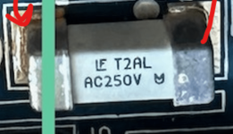
The ceramic fuse is 2 amps, so maybe the power does not go through the fuse.

Can you show good high resolution images of the back of the board?


1702701019144.png

1702701153274.png


AC250V 2A 12.10 x 4.5 x 4.5 mm LF T2AL250V 0465002.DR SMD 4717 Fuse

0.476" L x 0.177" W x 0.177" H (12.10mm x 4.50mm x 4.50mm)

LITTELFUSE 0465002.DR 465 Series Time Lag 250 V 2 A 12.1 x 4.5 mm SMT NANO2 Ceramic Fuse.​


GLX-PCB-MAIN PRO-LOGIC SYSTEM BOARD​

I will take pictures tomorrow as its pitch dark outside right now but this is a brand new board and all components seems perfect without damage to any traces, burnt fuses, swollen capacitors etc etc. update. this is a night picture. The loose oranges are because I was testing
 

Attachments

  • IMG_6078.jpg
    IMG_6078.jpg
    147.3 KB · Views: 4
Last edited:

GLX-PCB-MAIN PRO-LOGIC SYSTEM BOARD​

I will take pictures tomorrow as its pitch dark outside right now but this is a brand new board and all components seems perfect without damage to any traces, burnt fuses, swollen capacitors etc etc.
Well, something must be wrong with it if the voltage is good for the yellow wires but not for the orange wires.

The voltage goes from the top yellow to the 20 amp fuse and then from the fuse to the top orange.

The other side goes from bottom yellow through the board to bottom orange.

So, either the top path is bad or the bottom path is bad or maybe both are bad.

Remove the wires and check continuity (Resistance/ohms) with the power off from top yellow to top orange and from bottom yellow to bottom orange.
 
Well I think you are on to something. Top yellow to top orange has "NO" continuity
Bottom yellow to Bottom orange has continuity. This is BIG! (maybe promising). Now we have to figure out path between top yellow and orange and whats happening. I will remove board tomorrow and look at soldering. Any other thoughts? and thank you (and everyone else)
 

Enjoying this content?

Support TFP with a donation.

Give Support
I am not sure but I think there maybe a component between the top orange and yellow. It sits behind the fuse. ? voltage regulator?
Check the fuse.

The board does not say Hayward or Goldline anywhere.

Is it genuine Hayward or generic?
I can not believe this!!!! I thought I took every effort to buy new and OEM YOU are RIGHT!!!!! I THINK ITS A COUNTERFEIT (is there such as thing as generics or is it counterfeit). Explains a lot
 
when I look at the bottom of my old board it appears to me that the yellow goes to fuse and the fuse possibly through a voltage regulator that sits behind the fuse. My fuse is good btw. The orange terminal goes to middle lead of voltage regulator and the yellow top goes to 1st lead. So correct me if I am wrong the Yellow to orange connection has a voltage regulator in between.
 
Last edited:
He did not say genuine. "NEW - GLX-PCB-Main Main PCB Printed Circuit Board for Hayward AquaLogic AquaPlus"
That's fraud because the part number is a Hayward part number.

A different manufacturer cannot use the same part numbers.

They have to identify the manufacturer.

Their label is intentionally misleading.

In any case, I don't know if it goes through a voltage regulator or not.

I don't know why it would need a voltage regulator.

Can you show the voltage regulator?

You can probably just skip the orange wires and connect the yellow directly to the rectifiers where the orange wires connect.

You should install a 20 amp inline fuse in one of the yellow wires.

I would send the fake board back for a refund based on fraud and misrepresentation.

If you want to try to connect the yellow directly to the rectifiers, you do it at your own risk.

I do not know if it will work or if it is safe to do this.

I do not recommend doing it as it might have unintended unexpected problems that might damage the system or cause other damage.
 
Thats an interesting idea skipping the oranges all together! The part I though might be a voltage regulator by its looks sits right behind the yellow fuse and infront of transformer. 3 prongs
 

Enjoying this content?

Support TFP with a donation.

Give Support
Thread Status
Hello , This thread has been inactive for over 60 days. New postings here are unlikely to be seen or responded to by other members. For better visibility, consider Starting A New Thread.