Automation of INTEX SWG

Apr 20, 2021
14
Spain
Pool Size
10700
Surface
Vinyl
Chlorine
Salt Water Generator
SWG Type
Intex Krystal Clear
Hi all,
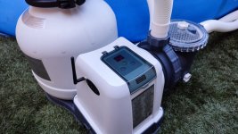
I've been reading several ideas about how to automate the Intex SWG for instance using a wifi smart plug. I have an eedomus at home. This works with a z-wave network, but lots of devices (i.e. wifi devices) can be integrated.
My initial idea was to modify the SWG to integrate an Arduino ESP-32, which costs less than $4 and it has very interesting capabilities, for instance Wifi connectivity.
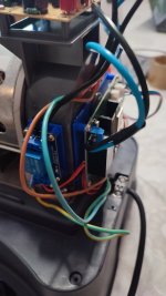
Examining a little bit inside the device I've found out that it has 2 PCBs, one with the 7 segment display, leds and a led drive controller TM1650, and a second one that controls everything with a microcontroller. Between both boards there is a 4 pin cable (SDA, SCL, +5V, GND) which carries an I²C bus over SDA (Serial Data) and SCL (Serial Clock). This kind of communication bus can have one master and multiple slaves. I'm this case, the LED driver is the salve. I thought about listening in that bus with the Arduino, but master uses slave address to send data, and having 2 slaves with the same address is not actually a good idea, and at this point things become a little bit more complicated.
So... KISS principale (Keep it simple stupid), and now comes what I'm planning to do.
1. Connect every positive from the status leds to a different input of the Arduino to guess the status
2. Use NPN transistors with the base connected to some other I/O pins of the Arduino, and this way bypass the the buttons.
3. Create a REST API in the Arduino ESP-32 to be able to request SWG current status and to be able to send any command (exactly the same than pushing any button physically).
4. Make the ESP-32 able to make HTTP requests to automatically report any issue or state change.

This way, the SWG integration with Smart Centers like mine would be a pice of cake, and there you could manage everything, and if the device loses power, when power comes back everything works as the brain is the smart center.

What do you think about my idea? Any feedback or improvement?

Thank you!
 
Last edited:
Interesting hack. Appreciate progress reports and how it works out. I think few Intex owners have the technical chops to do what you describe.
 
  • Like
Reactions: tonyflores1006
Interesting hack. Appreciate progress reports and how it works out. I think few Intex owners have the technical chops to do what you describe.
I've received all materials needed for the hack this week, and I've made some progess, but still work to do. Below I'll detail my current achievements after two afternoons working on that...

Achieved:
- Device creates an Acces Point to be able to connect to It and then configure the Wi-Fi Network.
- Device connects properly to the configured Wi-FI network.
- Device accepts HTTP API call request to turn ON/OFF the SWG, and it works! So I can turn ON/OFF remotely using a computer, cell phone, etc...
- Device reads the power led status of the SWG (almost done because is not actually a continuous signal, it's a pulse signal with a frequency of 300Hz aprox.)
 
  • Like
Reactions: setsailsoon
New updates!!!
I've totally changed the approach after some research. The control PCB uses a TM1650 integrated circuit to manage the two digit display, the status leds and read the buttons. Other microcontroller in the main PCB sends to the control PCB the current status and makes requests to read the buttons. The communication bus is not actually an I2C, but quite similar.
I managed to read and understand all the communication between both boards using an ESP32, and also I'm able to send data to the control board. Next step is to be "in the middle", which will allow me to introduce some messages like turn on the SWG, so I'm no longer need to use a transistor to mimic the buttons (I hope the ESP32 is fast enough to be in the middle without causing delays).

To sum up... The 4 pin wire from the control board will be connected to the new board with the ESP32, and another cable will be connected from the new board to the main one. No need to solder anything nor modifying the machine, so totally reversible in case you need the warranty and this device will become an IoT.
I will share the exact list if components needed (all available in AliExpress), as well as schematics, information that I used and firmware to allow anyone to do it just following the steps. I'm really happy with the results I'm getting.
After that, I'll modify the project to adapt it to a Crystal Clear water pump so both devices can be integrated for instance into Home Assistant.

I cant wait. Keep me updated, this is something I have been looking for.
 
  • Like
Reactions: tonyflores1006
Cool project. Exactly what i was looking for. I really would like to automate my SWG with home assistant.
My pump has an "timer/off/on" switch so that can be turned on and off just with an power switch.
But i always have to manually press the button on the SWG to start it. :(
 

Enjoying this content?

Support TFP with a donation.

Give Support
New updates... I also have an Intex Sand Pump and used the project for that too, even taking into account that is not needed as the pump starts automatically if the power is lost.

Features working:
- ON/OFF/STANDBY control via API. A relay is used to completely turn off the machine.
- Display code and status leds information via API
- Self clean can be configured via API.
- Wifi manager with Access point to configure the wifi easily using any other devices Ike an smartphone.
- Display brightness configurable via API.
- Over the air firmware update (OTA).

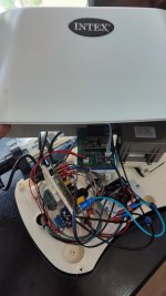
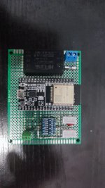
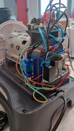
I've attached a couple pictures of everything installed. On the left next to the temperature sensor there is the relay module, and the main board of the project is on the right with the serial buses and cables to control the relay attached.
Now I'll start preparing the how-to and BOM, as well as the source code and share it. Stay tuned!

IMG_20210708_182015.jpg
 
You might want to check this thread out.

That's a really interesting job, but my aim was to make something that can be completely reverted in case of having warranty issues, and also to keep the default machine behaviour if you are not operating it via any integration with any automation center. I've extended the functionality to make it an IOT device but still can work as factory default.
 
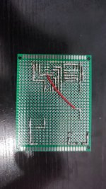
Bonus pictures of the project adapted and working for the Intex Krystal Clear pump. I could order the PCBs, but as I only need this one for myself and this way works, then is OK for me. The blue supports of the relay and main boards are made by me using with my 3D printer and we're designed using Fusion 360. In the last picture, a wifi antenna can be seen... This was necessary due to the distance with my router.

IMG_20210629_203916.jpgIMG_20210629_203921.jpgIMG_20210704_184808.jpgIMG_20210704_184821.jpgIMG_20210705_180738.jpg
 
I've been testing it for more than a month and solving some bugs and now seems to work fine, still not a final release but definitely usable. I'll share everything as soon as possible, as I've just came back from vacation and have to look for the time to prepare everything.a
 
Hey again Tony. Do you think it will be ready here in the next week or so? Winter is coming so I plan on bring the system inside as recommended by the manufacturer but when I do so I wont be able to test it out any due to it not getting fed water and everything else that it goes through. I also will need to purchase the parts which normally take a week to get here as well. Thanks!
 

Enjoying this content?

Support TFP with a donation.

Give Support
Thread Status
Hello , This thread has been inactive for over 60 days. New postings here are unlikely to be seen or responded to by other members. For better visibility, consider Starting A New Thread.