I am currently installing an AquaLink PDA-PS4 automation system.
I have a Pool and Spa combo where the spa spills over into the pool. Spa and pool can be isolated depending on valve positions.
Pump is a Jandy VSP (VSPHP270AUT)
Heater is a Jandy JXi
Currently the pump controller is a Jandy iQPUMP01 interface.
Goal in all of this is to remotely control and monitor the heater, and be able to have a pool mode that heats to one temp, and a spa mode that heats to another. This is for an airbnb type rental and can't have guests messing with the valves potentially destroying equipment or busting lines. I have 2 pvas to achieve this and this is where I've hit the wall. Wiring the PCB has been easy and straightforward thus far however..

I seem to be missing the white 3-pin connectors at the top right corner of the board. According to the wiring diagrams this is where my PVAs will connect to. I also don't have the screw connectors for the green 10pin for my heater and temp sensors to connect to.
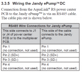
I have the transmitter for the PDA remote and an AquaLink 2.0 wireless network control interface. With both of those connected I have no space left for the pump itself. I have read other posts on here saying that you can use one connector for multiple devices but I am confused as to how that would work. Does the 4pin red connection exist simply to provide power? Could I simply cut the cable for the iQPUMP01 and insert them into the connector for the transmitter or aqualink network interface? Would I retain the variable speed function of the pump? The cable from the IQPUMP01 to the pump is the only cable I have for the pump connection and the one end lf the cable has the red connector but the other end goes into the interface. If I open up the iQPUMP01 will I find a red 4pin connector inside that I can use or is it soldered to its circuit board?
I need to have this system operational by the 26th. I've probably waited too long to make this a painless process and that's on me but any advice of how to get everything connected is greatly appreciated.
I have a Pool and Spa combo where the spa spills over into the pool. Spa and pool can be isolated depending on valve positions.
Pump is a Jandy VSP (VSPHP270AUT)
Heater is a Jandy JXi
Currently the pump controller is a Jandy iQPUMP01 interface.
Goal in all of this is to remotely control and monitor the heater, and be able to have a pool mode that heats to one temp, and a spa mode that heats to another. This is for an airbnb type rental and can't have guests messing with the valves potentially destroying equipment or busting lines. I have 2 pvas to achieve this and this is where I've hit the wall. Wiring the PCB has been easy and straightforward thus far however..

I seem to be missing the white 3-pin connectors at the top right corner of the board. According to the wiring diagrams this is where my PVAs will connect to. I also don't have the screw connectors for the green 10pin for my heater and temp sensors to connect to.
I have the transmitter for the PDA remote and an AquaLink 2.0 wireless network control interface. With both of those connected I have no space left for the pump itself. I have read other posts on here saying that you can use one connector for multiple devices but I am confused as to how that would work. Does the 4pin red connection exist simply to provide power? Could I simply cut the cable for the iQPUMP01 and insert them into the connector for the transmitter or aqualink network interface? Would I retain the variable speed function of the pump? The cable from the IQPUMP01 to the pump is the only cable I have for the pump connection and the one end lf the cable has the red connector but the other end goes into the interface. If I open up the iQPUMP01 will I find a red 4pin connector inside that I can use or is it soldered to its circuit board?
I need to have this system operational by the 26th. I've probably waited too long to make this a painless process and that's on me but any advice of how to get everything connected is greatly appreciated.


