AquaLink PDA install.. I've hit a wall

Meathead16

Member
Jan 12, 2022
9
Phoenix, AZ
I am currently installing an AquaLink PDA-PS4 automation system.

I have a Pool and Spa combo where the spa spills over into the pool. Spa and pool can be isolated depending on valve positions.
Pump is a Jandy VSP (VSPHP270AUT)
Heater is a Jandy JXi
Currently the pump controller is a Jandy iQPUMP01 interface.
Goal in all of this is to remotely control and monitor the heater, and be able to have a pool mode that heats to one temp, and a spa mode that heats to another. This is for an airbnb type rental and can't have guests messing with the valves potentially destroying equipment or busting lines. I have 2 pvas to achieve this and this is where I've hit the wall. Wiring the PCB has been easy and straightforward thus far however..

20221222_173452.jpg

I seem to be missing the white 3-pin connectors at the top right corner of the board. According to the wiring diagrams this is where my PVAs will connect to. I also don't have the screw connectors for the green 10pin for my heater and temp sensors to connect to.

I have the transmitter for the PDA remote and an AquaLink 2.0 wireless network control interface. With both of those connected I have no space left for the pump itself. I have read other posts on here saying that you can use one connector for multiple devices but I am confused as to how that would work. Does the 4pin red connection exist simply to provide power? Could I simply cut the cable for the iQPUMP01 and insert them into the connector for the transmitter or aqualink network interface? Would I retain the variable speed function of the pump? The cable from the IQPUMP01 to the pump is the only cable I have for the pump connection and the one end lf the cable has the red connector but the other end goes into the interface. If I open up the iQPUMP01 will I find a red 4pin connector inside that I can use or is it soldered to its circuit board?

I need to have this system operational by the 26th. I've probably waited too long to make this a painless process and that's on me but any advice of how to get everything connected is greatly appreciated.
 
You can connect 4 items to the 2 RED connectors - each can handle 2 pieces of equipment. So one RED connector can be wired with the AquaLink 2.0 antenna and the PDA. Then use the other RED connector for your pump. I am not totally familiar with the Jandy pump but can you run a RS485 cable from the pump to the 2nd RED connector? Remove the connection for the IQPump controller.

You definitely need the GREEN connector to connect the heater & temperature sensors. Did that not come with the PCB? Or maybe it is on the old PCB?
 
I am currently installing an AquaLink PDA-PS4 automation system.

I have a Pool and Spa combo where the spa spills over into the pool. Spa and pool can be isolated depending on valve positions.
Pump is a Jandy VSP (VSPHP270AUT)
Heater is a Jandy JXi
Currently the pump controller is a Jandy iQPUMP01 interface.
Goal in all of this is to remotely control and monitor the heater, and be able to have a pool mode that heats to one temp, and a spa mode that heats to another. This is for an airbnb type rental and can't have guests messing with the valves potentially destroying equipment or busting lines. I have 2 pvas to achieve this and this is where I've hit the wall. Wiring the PCB has been easy and straightforward thus far however..

View attachment 466099

I seem to be missing the white 3-pin connectors at the top right corner of the board. According to the wiring diagrams this is where my PVAs will connect to. I also don't have the screw connectors for the green 10pin for my heater and temp sensors to connect to.

I have the transmitter for the PDA remote and an AquaLink 2.0 wireless network control interface. With both of those connected I have no space left for the pump itself. I have read other posts on here saying that you can use one connector for multiple devices but I am confused as to how that would work. Does the 4pin red connection exist simply to provide power? Could I simply cut the cable for the iQPUMP01 and insert them into the connector for the transmitter or aqualink network interface? Would I retain the variable speed function of the pump? The cable from the IQPUMP01 to the pump is the only cable I have for the pump connection and the one end lf the cable has the red connector but the other end goes into the interface. If I open up the iQPUMP01 will I find a red 4pin connector inside that I can use or is it soldered to its circuit board?

I need to have this system operational by the 26th. I've probably waited too long to make this a painless process and that's on me but any advice of how to get everything connected is greatly appreciated.
You can have more than one set of wires in the red connectors at the top left of the board. If by PVA you mean valve actuators (JVA?), they connect in the sockets on the bottom right of the board. The sockets are labeled for suction, return, and two auxiliaries.
 
  • Like
Reactions: HermanTX
My mistake, I meant JVA, by PVA I was thinking Powered Valve Actuator but in thinking about it all actuators are powered lol

I should have said GVA as the 2 VA's I'm using are Hayward Goldline GVA-24 Valve Actuators that I grabbed from another one of my pools that no longer had a use for them. I'm hoping they are all compatible with eachother. Any reason they wouldn't be?
 
Last edited:
I seem to be missing the white 3-pin connectors at the top right corner of the board. According to the wiring diagrams this is where my PVAs will connect to.

You mean JVA actuators?

The 3 pin male connectors come with the actuator attached to the cable.

I also don't have the screw connectors for the green 10pin for my heater and temp sensors to connect to.

You need to find that. Pricey little sucker. Jandy Zodiac 6610 Terminal Bar


Jandy charges ridiculous prices for the red 4 screw and green 10 screw terminal blocks. They are called "Riacon" terminal blocks.

Metz part number 31007110 is the 10 pin block, Digi-Key Part Number 31007110-ND

I have the transmitter for the PDA remote and an AquaLink 2.0 wireless network control interface. With both of those connected I have no space left for the pump itself. I have read other posts on here saying that you can use one connector for multiple devices but I am confused as to how that would work.

You can put any number of wires under one screw. Two wires under each screw work fine. More than that does not work well. So with two red RS-485 connectors you can connect four devices.

Jandy sells a multiplex board if you need to connect more than four RS-485 devices. Some folks have wire nutted more wires together and it works sometimes but can get flaky.

Does the 4pin red connection exist simply to provide power?

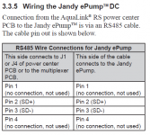
Screws 1 (red) and 4 (green) are power.

Screws 2 (black) and 3 (yellow) are RS-485 data.

Could I simply cut the cable for the iQPUMP01 and insert them into the connector for the transmitter or aqualink network interface? Would I retain the variable speed function of the pump? The cable from the IQPUMP01 to the pump is the only cable I have for the pump connection and the one end lf the cable has the red connector but the other end goes into the interface. If I open up the iQPUMP01 will I find a red 4pin connector inside that I can use or is it soldered to its circuit board?

Open up the pump and you will find the IQpump is plugged in. Unplug it as you do not use it with the AQualink and connect the pump to the Aqualink board RS-485 red connector using a four wire cable.

1671762629735.png

 
Last edited:
I should have said GVA as the 2 VA's I'm using are Hayward Goldline GVA-24 Valve Actuators that I grabbed from another one of my pools that no longer had a use for them. I'm hoping they are all compatible with eachother. Any reason they wouldn't be?

The actuators are all compatible.

To mount an actuator, you have to remove 4 screws and install 4 longer screws.

The problem with using a valve actuator from one brand and a valve from a different brand is that the screws have a different thread.

The screws are self tapping and they will bite into the existing plastic threads, but it will damage the threads.

By using the same brand, the thread is the same and you should be able to avoid cross-threading.

 
I'm working on this right now and just discovered the thread issue. They would ha.. hopefully Ace will have the screws I need.

I see the iQPUMP01 connection to the pump, but since I don't need it anymore and am going to have to connect the wires in with another RS485 connector anyway, I can leave the iQ connector end plugged into the pump, then just cut the cable leading to the iQ, strip the wires and connect them into the red 4pin connector that I have for the other interface and all is happy with the pump?
 
Do not cut the iQPump01 wire with the pump powered. I would disconnect the iQ connector from the pump before cutting the wire.

Always power down the Aqualink and any RS-485 devices before touching the RS-485 connections.

For the pump you only connect pin 2 (black) and pin 3 (yellow) wires to the Aqualink board.

1671766300754.png

1671765978314.png
 
Last edited:

Enjoying this content?

Support TFP with a donation.

Give Support
I can leave the iQ connector end plugged into the pump, then just cut the cable leading to the iQ, strip the wires and connect them into the red 4pin connector that I have for the other interface and all is happy with the pump
Yes - just get the wires in the correct order on the RED Connector attached to the AquaLink PCB.
Refer to the manual noted in post #7
 
Thank you everyone for your replies and support! I was not expecting to be able to be able to post and get replies practically in real time as I was working on it. This is the first forum that I have ever experienced that on and you guys are awesome! Thanks to your help I was able to finish the install successfully.
 
  • Like
Reactions: HermanTX
Thread Status
Hello , This thread has been inactive for over 60 days. New postings here are unlikely to be seen or responded to by other members. For better visibility, consider Starting A New Thread.