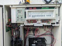
ph Dosing pump question

I like both these ideas. I think the venturi barb idea would provide the best flow . I would just need to find one that will fit inside 1/2" NPT threads and a larger barb for 1/2 tubing.

If I simply convert the supply line from 1/2" to 3/8" for the majority of the run, I wonder if that would create enough of pressure difference?
 
Do you think two of those fittings mounted in a straight pipe would work for the OP, or does it need to narrow, like it does in that EZ-Flo valve setup?
I don’t know. At this point it becomes a science experiment.
 
  • Like
Reactions: Dirk
I like both these ideas. I think the venturi barb idea would provide the best flow . I would just need to find one that will fit inside 1/2" NPT threads and a larger barb for 1/2 tubing.

If I simply convert the supply line from 1/2" to 3/8" for the majority of the run, I wonder if that would create enough of pressure difference?

You can estimate the pressure drop using the sudden contraction formulation:


The plumbing curve for a 1/2" to 3/8" is:

Head (ft) = 0.0287 * GPM^2
Head (PSI) = 0.0125 * GPM^2

Of course you need to determine the flow rate through the tubing. But you can see there won't be much of a pressure drop unless the flow rate is high and the flow rate is not high unless there is a higher pressure differential so this is unlikely to work.

Where did you end up putting the supply and return lines?

The further apart the better. For example, if you have the supply right after the filter and the return somewhere after the heater might work.
 
@mas985, can you look at post number 18 above? Does this setup divert water through my fertilizer tank only because the barbs of the injectors are facing opposite directions? Or does the narrowing of the PVC (from the reducer, thru the valve, then back thru the other reducer) do the magic? Or both?
 
@mas985, can you look at post number 18 above? Does this setup divert water through my fertilizer tank only because the barbs of the injectors are facing opposite directions? Or does the narrowing of the PVC (from the reducer, thru the valve, then back thru the other reducer) do the magic? Or both?
I did miss that.
1740697910123.png
The blue source fitting will have higher pressure than the green return fitting due to the orientation of the fitting sloped opening and the direction of flow. Pressure is always higher on the front end of an obstruction and lower and the trailing end of an obstruction. Although I would not expect a very large pressure difference, it is likely sufficient to move water through a closed pressurized system.

It is hard to know for sure if that would or would not work for the OPs setup as there may be additional pressure loses in that system vs yours but it would probably be worth a try given the fittings are pretty reasonable.
 
  • Like
Reactions: Dirk
but it would probably be worth a try given the fittings are pretty reasonable.
Thanks for weighing in. And that drawing explains well the orientation of the injectors. As Allen pointed out, it's the OP's science experiment at this point. I offered this version because, as you say, the cost and impact to the existing plumbing would be minimal.
 
So unfortunately the smaller line to try to create a pressure differential did not work. I've been searching for hours for some type of of fitting like the one Dirk posted but for larger than 1/4 line


1000013402.png
It doesn't specify what size threads so I'll call them on Monday and also see the they have larger fittings. They do sell a higher flow version with what appears to be much larger fittings. Hopefully they are 1/2 npt threads. EZ-FLO - HI-FLO Coupling Connections w/ Ball valve | EZ Flo Injection Systems

If I can't find a fitting that will work, I'm thinking maybe some type of small booster pump to help with the flow.
 
  • Like
Reactions: Dirk
Problem solved! Thanks all for helping me stay determined to find a solution. As I was throwing away the garbage tonight, I noticed I had 3 smaller saddles the kit came with. I took one more look at my equipment pad and found a lonely pipe that just happened to be the same size for the saddles. This is for a RETURN jet on a sun shelf which is rarely used, so there's never any pressure on that line.

Drilled a new hole, connected it to the line, and the water was flowing very generously so I closed the ball valve almost all the way. I tested it with the bubbler running at many different RPMs with dye in the line and it's flowing perfectly.

Red: supply line for the flow cell
Purple: old location of return line from the flow cell
Blue: new return line for the flow cell, connected as far possible down the line.

1000013434.jpg
Just have to go to Home Depot tomorrow to get a 1/2" cap to screw on the old saddle so I can remove the ball valve there that's no longer needed.

Now if only I could find a flow switch that could thread into that old saddle. That'll be my next project.
 
In continuation of my Hanna BL100 project that originated in this thread, I want to add a sensor to the acid doser so that it does not run when the pool is in Spa Mode only. I'm afraid it could cause injury if something goes wrong and overdoses the spa. There's not enough in the tank to really cause harm if it dumped it all in the pool, so it's only a concern if it's in Spa Mode.

I was thinking, rather then adding a flow switch and trying to plumb that in, I could piggyback off the position of the Jandy Actuator. I first purchased the limit switch on Amazon. https://a.co/d/4y08dj9

It's built really well (potted and fully weather proof) but I'd have to mount it to the top of the JVA somehow. I bought epoxy not realizing that the sensor is all metal.

I then remember the inside of the Jandy Actuator has limit switches that detect when to stop the motor from turning. Unfortunately I believe those switches have 24v through them, and the Hanna BL100 only has an input for a dry contact.

I need ideas on how to convert the position of the limit switch to a NO or NC dry contact, preferably something that is small and can be stored inside of the housing of the actuator. Anybody have any ideas? Here's the switch:

1000013435.jpg
 

Enjoying this content?

Support TFP with a donation.

Give Support
You can use a piece of 4x4 lumber and build off that after the following. Assuming you have 2" pvc you'd core a 2.375" in hole in it. After that you'd cut through the center of the hole so in the end you have the two halves which would be slightly off round due to the loss of the cut. Then you would screw the two halves together around the pipe and it rather snug. From there you can make whatever you need as your first plan was to do.
Screenshot_20250301_210229_Gallery.jpg
 
  • Love
Reactions: ChristopherDB
6.1 DIP Switch Functions.

S1 DIP #1 ON- AUX 1 Controls Pool Cleaner.

If you installed a booster pump for a pool cleaner, the relay coil for the booster pump must be plugged into the AUX 1 relay socket. If a non-booster pump
cleaner is installed, plug the JVA into the cleaner JVA socket.

Turn ON DIP Switch #1.

• Main filter pump turns on whenever cleaner turns on.

• Cleaner will not turn on until filter pump has been on for three (3) minutes (to ensure priming of system).

• Cleaner turns off when water circulation is to spa.

• Cleaner turns off when spa spillover feature is activated.

• Cleaner turns off for three (3) minutes when solar is activated (to ensure air is purged from the system).

• AquaLink RS control panel display reads “CLEANER” rather than “AUX 1”
 
I love this idea. Would simplify everything. Yes I have a suction cleaner which is automated by a JVA on Aux 1.

I do not have a relay attached to aux 1 but I have an extra relay I could attach.

My dip switch has cleaner OFF. Previously I had it on, but I discovered a bug years ago that Jandy failed to acknowledge was an issue. When the cleaner dip switch was on, I would randomly get an error in iAqualink when I wanted to turn on the spillover, saying the cleaner was running when it wasn't. (Or maybe it was the opposite, where the spillover was not on but the cleaner thout it was). I had since disabled the spillover dip switch and just have the JVA for that assigned to the AUX 3. It would happen once every couple weeks. It was not within the cool down period either and doing a "Cancel Delay" wouldn't help either. The only way to recover from this would be to reboot the entire panel. Additionally, the solar AUX is connected to a Jandy SMARTJVA that I want to be able to operate when the cleaner is running, so setting the dip switch to Cleaner would prevent this from getting power. Unfortunately I'm using all AUXs either through a JVA assignment or a relay.

I'll have to go back and review how I programmed everything and figure out if I can make adjustments.
1000013436.jpg
 
You can use the power to the actuator to control a relay.

When the return valve actuator is sending water to the Pool, the Relay will be powered.

The relay is the same as the other relays except it is 24 VAC instead of 24 VDC.


I'm thinking I could connect a relay to AUX 7 which I have the skimmer JVA assigned to it. When the skimmer is open, the AUX could be powered and then power the PH doser. Since the skimmer is open the major of the day (except when the cleaner is running) it would give it enough time to run. I would just have to make sure to turn the skimmer off when using the spa to shut down the doser. Not sure if I could automate that?
 
You can use the power to the actuator to control a relay.

When the return valve actuator is sending water to the Pool, the Relay will be powered.

The relay is the same as the other relays except it is 24 VAC instead of 24 VDC.


So for the actuator that controls the flow from pool/spa on the pressure side, would I splice in the relay to that same connection?
 
The valve actuator sends 24 VAC to Black and Red or Black and White depending on the actuator position.

Power the relay coil in parallel to the Black and Red or Black and White depending on which is powered for the return actuator to point to the Pool Return.

1740884050778.png
  • Black - Common
  • Red - Switch Leg
  • White - Switch Leg
 

Enjoying this content?

Support TFP with a donation.

Give Support