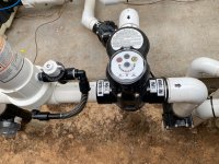
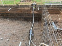
So I figured it out and tested it. When it's on the side with just one pipe it activates the skimmer by the sun shelf and turns off the other two. When I turn it the other way, the other skimmer and presumably the main drain both get suction. This theory matches up with some of the piping pictures I have where that deep end skimmer and main drain where piped together. Or I'm mistaken.
Well you tested correctly and your results confirm how the pipes are marked. I just don't know why it is done like that as you do not have any capability to maximize skimming by turning the main drain to very low suction or off. I went back and looked at old posts (see #191, 192, 193 and 194) where it was confusing then because the plumbing diagrams did not match the pictures (reality) and we made some assumptions that the 2 suction pipes to the left were for each skimmer but that assumption has been proven incorrect based on your testing.
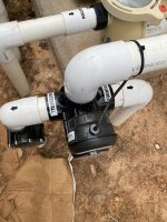
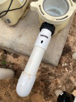
Should I bring this up to the pool builder and tell them that it's done wrong? Or do some builders do it this way? Here are some plumbing pictures I had. From the looks of it that one skimmer looks like it's connected to the main drain then goes out and that's why it's setup like that on the equipment pad. But if they were on the same line then no reason to have 2 pipes?
I think the PB should try to explain how you will maximize skimming on its current configuration and how do you utilize the independent lines for each skimmer if they are not controlled by any valve? Also ask, if you just wanted to have suction from the main drain for example to suck up dirt that fell in your pool or to lower the water level below the skimmers, how do you accomplish that? Based on what is shown, you cannot isolate the main drain only for suction unless you plug a skimmer.
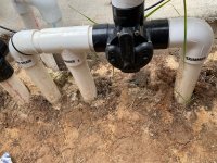
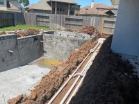
What I have seen in the forum is that there is no "standard" for plumbing configuration. Also, it would be good to show the PB the 2 pictures of the main drain with 1 pipe going to the skimmer and the other pipe go the opposite direction. Ask how do they link up at the equipment pad? What is the function of the main drain pipe going to the skimmer?
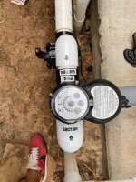
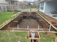
FYI, some skimmers are set up to close the skimming suction line when water level drops and then it opens up the line from the main drain. This protects your pump from sucking in air. But you have 2 skimmers and only 1 appears to be set up that way so if you have low water level the other skimmer will suck in air. Furthermore, you have a auto-fill so your water level should remain fairly constant unless the auto-fill float breaks. Maybe the picture is deceiving and that main drain line only appears to connect to the skimmer but it may just run next to it and it is an independent line to the equipment pad. Sorry to ramble on but just trying to provide any possible explanation for why it is set up the way it shows in your pictures.
Ideally, as what was discussed back in those early posts from July, it to put a Jandy 2 way valve on each of those 3 lines (the 2 skimmers and the 1 main drain) then you can make any adjustment using those valves to control pool suction. It means ripping out what has already been done but better to do it now. If your PB stumbles as to how all of this is to function as currently set up, then you have good reason to say, rip it out and put in the valves to control each suction line.
Hope this helps.