Problem:
Components:
Operation Theory:
Use Case:
Now that the pump can be powered on remotely, I've implemented a best practice regarding my pump maintenance procedures. I unplug the pump's power anytime I'm needing to close the valves, deal with the skimmer ect. Basically anytime I want to pump to be off for longer than a few seconds. This is because my smart home does not yet have the "guy is working on the pump so don't turn it on" sensor. Should would hate to be working on the skimmer with the valves closed and suddenly the pump powers on!
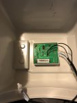
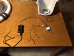
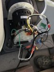
I realize this post is lacking detailed instructions on how to implement the above. I will attach images of my setup that might better serve as a guide than simple text. Also most of the complexity was the configuration of the Qubino ZWave device into the ZWave hub which is out of scope for this forum.
I'm sure there are more economical ways to convert this pump to be smart home compatible. For instance there are many WiFi devices that will be cheaper than the Qubino.
Finally -- I'm posting this to describe how I solved a problem. It most likely is not the easiest, safest, or most economical solution. If you try it and break your pump, I'm not responsible.

I got the Intex 16" Sand Filter Pump (Model SF60110-2) to replace the small Intex Cartridge pump that came with our 18' above ground pool. The outgoing pump's schedule was controlled by a zWave outdoor smart plug and life was good.
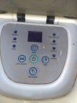
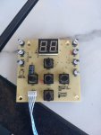
Well... the new sand filter pump is equipped with a digital timer and uses this circuitry to power on the pump by a momentary press of the power button on the control panel. Unfortunately for my desired setup, the sand pump requires the physical press of the control panel's power button any time there is an interruption in power. Meaning, the outdoor smart plug can turn the pump off but cannot turn it back on. Secondary issue is that power outages will require someone to go outside to press the button.
So my mission to make this pump work with my smart home began. Surprisingly I was unable to find a lot of information regarding this particular problem (not powering on after power disconnect) on the internet. I quickly eliminated options to direct wire the pump motor to A/C. I did not want to bypass any motor self protections, ect. So I concentrated on ways to emulate the press of the power button.
Components:
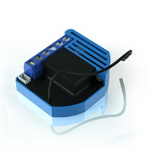
- Qubino Z-Wave Plus Universal Relay with Dry Contact Switch ZMNHND3 ** manufacture list this as indoor only with a temp range 14 to 104F. Its install under the pump's cover and I've been keeping the pump in the shade. So far so good but its a risk.
- Enclosed AC/DC Power Relay with Protection & De-Bounce. Screw Terminals. 120V Trigger Input
- 22 - 16 Gauge Wire Disconnect Pairs
Operation Theory:
The Qubino connects to my existing smart home (I use SmartThings). A command is sent from the smart home to Qubino to momentarily close a circuit. This circuit is connected to the Intex's power button. So when Qubino shorts the circuit, the pump believes the power button has been pressed. -- Okay great. Now we can turn the pump on and off. But how do we know if the pump is already on? -- see next
Intex's pump motor is powered on. The motor's power line (Black) is now energized which is connect in parallel to AC/DC power relay. When the AC/DC power relay senses the 120v power, it closes its 'Common / normally open' circuit which is monitored by Qubino's I2. -- Now we can detect the pump's status.
Use Case:
Why even bother? I mean the pump already has a timer.
All I can say it that it's a smart home person thing. These smart home systems can monitor just about anything you can think of. Some are more versatile than others but all can provide a more complex schedule than a simple "run x hours per day". My pump starts 4 hours after sunrise. After 2 hours, powers back down. 3 hours later it runs another 2 hours. This repeats until evening where the pump runs solid from 6PM to 2 hours after sunset (This captures most of the evening June bugs in the skimmer). At night if the outside temperature drops below 36F degrees, the power will power on to protect the pipes from freezing.
Now that the pump can be powered on remotely, I've implemented a best practice regarding my pump maintenance procedures. I unplug the pump's power anytime I'm needing to close the valves, deal with the skimmer ect. Basically anytime I want to pump to be off for longer than a few seconds. This is because my smart home does not yet have the "guy is working on the pump so don't turn it on" sensor. Should would hate to be working on the skimmer with the valves closed and suddenly the pump powers on!
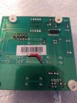
I realize this post is lacking detailed instructions on how to implement the above. I will attach images of my setup that might better serve as a guide than simple text. Also most of the complexity was the configuration of the Qubino ZWave device into the ZWave hub which is out of scope for this forum.
I'm sure there are more economical ways to convert this pump to be smart home compatible. For instance there are many WiFi devices that will be cheaper than the Qubino.
Finally -- I'm posting this to describe how I solved a problem. It most likely is not the easiest, safest, or most economical solution. If you try it and break your pump, I'm not responsible.


