Whisperflo VST wiring connection

VBV

Member
Dec 18, 2022
12
Hill Country, Texas
Hello All
I'm new to the group and would like to tap into your expertise.
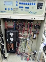
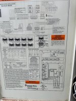
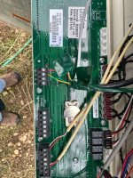
I am replacing a 9 year old Whisperflo single speed with a Whisperflo VST. I also have the cable, RS-485, PN356324z. The control panel is an Easy Touch Automation Controller #5K42. I controlled the previous pool equipment using my cell phone or locally, and would like to do the same now.
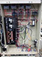
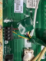
The manual that came with the new pump was a bit confusing to me regarding the electrical connection with the control I desire, ie. remote vs. external, and ect. I connected the yellow and green wires from the control cable to the COM port terminals and removed those that were already there. However, my controller does not seem to recognise the new pump and does not control it. If I am to connect more wires from the cable, am I to leave the current wires on the relays or remove them? Any input would be greatly appreciated.
 
Welcome to TFP.

The pump AC power, 120V or 240V, for VS pumps should be wired for constant power to the LINE side of the relay, not the LOAD side.

Post pics of the inside wiring of your EasyTouch cabinet.
 
You need to post larger pics. I can't see any details of the wire connections in the pic you posted.

Also show me where you have the RS-485 cable connected to the ET.
 
VBV,

Keep in mind that after you get the wiring correct, you will still have to tell the EasyTouch that you have a VS pump, and what speeds that you want each circuit to run and when you want the pump to run.

Do you have ScreenLogic or do you do programming via the little 3" display?

Thanks,

Jim R.
 
VBV,

If you have an Android style phone, you need two apps... ScreenLogic and SLConfig to set up the pump (any other things).

I am not at all sure if Apple phones need two apps or not. :scratch:

As Allen points out above, the pump needs constant AC power, so it should never be power through a relay... unlike a single speed pump which does need the relay to turn it on and off.

Thanks,

Jim R.
 
For the pictures, hover over picture name, then click the 480x640 and a larger, clearer picture is visible.
The top 2-pole breaker controls the pump. So I believe you are saying to move the leads to the pump from the load side of the contactor to the the lead side where the feed is landed for constant power to the pump. Then am I to use only the green and yellow wires from the cable as shown OR do I need to wire differently?
 

Attachments

  • aaa1.jpg
    aaa1.jpg
    78.9 KB · Views: 40
  • aaa2.jpg
    aaa2.jpg
    77.6 KB · Views: 32
  • aaa3.jpg
    aaa3.jpg
    76 KB · Views: 33
  • aaa4.jpg
    aaa4.jpg
    94.8 KB · Views: 65

Enjoying this content?

Support TFP with a donation.

Give Support
The apps will control the VST just fine. You need to tell the system you have a VS pump now. You do that in SLCONFIG.
 
For the pictures, hover over picture name, then click the 480x640 and a larger, clearer picture is visible.

The TFP server takes pics up to something like 3 to 5 MB. Larger then 480x640.


The top 2-pole breaker controls the pump. So I believe you are saying to move the leads to the pump from the load side of the contactor to the the lead side where the feed is landed for constant power to the pump.

Correct.

Then am I to use only the green and yellow wires from the cable as shown OR do I need to wire differently?
Your green and yellow wiring is correct.

You need to tell the ET you have a VS pump in its Configuration.
 
Will do. The yellow and green wires originally landed on COM PORT

That is correct.

.....should they be removed or should they be paralleled with the wires from the pump cable?

I have no idea where you are suggesting to connect wires to.

Do you have the VS pump set in the ET Configuration?
 
What does the wire with the taped over wires go to?

You sure the correct cable from the pump is connected to J20 Com Port?

aaa4-jpg.465723
 
What does the wire with the taped over wires go to?

You sure the correct cable from the pump is connected to J20 Com Port?

aaa4-jpg.465723
O
Originally, the white cable coming in from the top of the picture has four wires and all four were connected to J20 Com Port. I lifted the green and yellow wires and taped them off. Then, the cable from the pump is a black cable with eight wires. I landed the green and yellow wires from the pump on J20 Com Port. Is this correct?
 
Originally, the white cable coming in from the top of the picture has four wires and all four were connected to J20 Com Port.

What device does that white cable go to?

I lifted the green and yellow wires and taped them off. Then, the cable from the pump is a black cable with eight wires. I landed the green and yellow wires from the pump on J20 Com Port. Is this correct?

You have green and yellow connected from the black cable and red and black wires connected from the white cable? No, that is not correct.

Where does the white cable go to?

I also see a green cable. Where is that connected to and going to?

You can have two wires under each screw. You probably need the green and yellow wires from the white cable also connected to J20.

aaa4-jpg.465723
 
VBV,

In theory, you could have a thousand cables connect one com port. Of course, you never get all the wires in there. :mrgreen:

Every RS-485 device needs to be connected to your J20 com port. You can put several wires in each connector, or wire nut everything together, and just run a jumper to J20, it is up to you.

Your pump's cable should only have the Yellow and Green wires connected to J20
Your ScreenLogic cable should have all 4 wires connected to J20
It appears you have a third cable?? Where does it go??

I hope that you have the power off when moving the com port wires as it can easily damage the com chips if the power is on.

Thanks,

Jim R.
The white cable (4 wires) goes to the sending unit for wi-fi. The receiver is in the attic of my house near the router. As for the green cable......there is no green cable, these are the remaining 6 "unused" wires from the RS-485 cable. And yes, the power is off.
 

Enjoying this content?

Support TFP with a donation.

Give Support
Thread Status
Hello , This thread has been inactive for over 60 days. New postings here are unlikely to be seen or responded to by other members. For better visibility, consider Starting A New Thread.