WF-26 leaking, Superflo VS install

tcat

Silver Supporter
May 30, 2012
1,619
Austin, TX
Pool Size
17000
Surface
Plaster
Chlorine
Salt Water Generator
SWG Type
CircuPool Edge-40
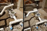
I'm getting a constant drip out the bottom of the flange when pump is on. When off air is sucked in and de filter drains. I ordered a new Superflo VS arriving Friday, but would like to fix the leak. Any odds as to which seal it might be? I have an old flange seal, but not a shaft seal. If I order a kit, may not be here before the new pump anyway. Losing about an inch per day, good thing it rained 2 inches a couple days ago!
 
I think our guess is as good as yours.

You get your new pump yet?
 
According to Amazon, tomorrow. Just in time since my 2 speed leak is getting worse. Have been lucky, with rain, pool gains an inch, then loses it. Supposed to get a shaft seal and plate seal Monday for it. Plan on working on it after my VS it's set up, probably sell it cheap.
 
Just got it, wow, so nice! How important is the distance from the input 90 to the input port? Says 5x diameter 5 x 2" = 10". If I use one coupling and their fitting, I'll have 7.5". If I add a second coupling I'll have 10.5", but the location of the output will mess up a bunch of existing pipes. I'll seldom run it on high since my cleaner is electric.
 
Don;t sweat it. The 3" will not make a difference.
 
  • Like
Reactions: tcat
Couple quick questions. All plumbed and electrical hooked up. Have not started it yet.

1. Meter between L1 and L2 reads zero. L1 or L2 to common reads 120v (but common not used). Can I assume I have 240v hooking L1 and L2 to pump (with ground)?

2. Is the pump basket clear lid supposed to come off it's frame? It did on my Whisperflo, but had tabs that prevent removal. No big deal.
 
Couple quick questions. All plumbed and electrical hooked up. Have not started it yet.

1. Meter between L1 and L2 reads zero. L1 or L2 to common reads 120v (but common not used). Can I assume I have 240v hooking L1 and L2 to pump (with ground)?

Sounds like you have 120V circuit to the pump.

Show us pics of the pump CB and pump electrical connections.
 
I've got 2 black, 2 white, 2 red, 1 green from breaker box. I left what was hooked up to timer and Stenner, and all that seems good.

I "thought" the 240v was the 2 bundles (red wire caps), so one wire from each of those goes to the pump. But with breaker on, I get zero voltage across those (I do get 240 to the Stenner, and 120 to an attached outlet). Thinking I need to attach one wire to a different place to get 240 to the pump.
 

Attachments

  • IMG_20200530_123313.jpg
    IMG_20200530_123313.jpg
    343.6 KB · Views: 4
I have seen too many crazy electricians to rely on wire colors. You have to identify the 240V feed wires from the CB.
 
All good! Picked wires that had 240 between them! Here's a before and after. Haven't played with speed, but primed ok and running at 1400. So nice to have a clear basket cover! Thanks!
 

Attachments

  • IMG_20200529_150246.jpg
    IMG_20200529_150246.jpg
    513.3 KB · Views: 3

Enjoying this content?

Support TFP with a donation.

Give Support
Odd, thought I had it licked, but tonight when some outdoor and pool lights were supposed to come on, nothing. There's an outdoor breaker box near the equipment, nothing tripped. Cable from there to the timer box (where I wired the new VS today), VS still on. Breakers in garage ok.

I'm guessing the wires in the timer box maybe feed back to the breaker box and then go out to lighting. So maybe I disconnected something I shouldn't have. The lights don't run off anything in the timer box, they're controlled by an external low voltage timer, which appears to have no power (it appears to be wired from the breaker box.)

I need to open the breaker box in the morning and see what's really going into the timer box. I know there's 2 reds, 2 whites, 2 blacks, and 1 green coming into the timer box. I assumed they were 2 circuits, but maybe one set is going out.

The Superflo VS is a great pump so far!
 
Giving up, time to call an electrician! Pump and Stenner working as they should, but can't get pool lights or landscape lighting on. Strange things happening... If I turn off the breaker that says "pool lights", my pump goes off. Not sure why wires for pool lights would be in my timer box. The small breaker box is crammed full of wires, can't tell what goes where. Crazy electricians, probably previous owner trying to diy (like me).
 

Attachments

  • IMG_20200531_092957.jpg
    IMG_20200531_092957.jpg
    326.5 KB · Views: 5
  • IMG_20200531_092720.jpg
    IMG_20200531_092720.jpg
    389 KB · Views: 4
You have three hot wires going into your panel - two hots paired with the 240V CB and one hot from the 120V CB.

You have the pump connected to one hot from the 240V CB and one hot from the 120V CB.

You never identified the 240V pair of hots that goes to the pump..
 
Here's the breaker in the garage that goes to the small panel outside. In the timer box there's 2 black and 2 red. 1 red has no voltage. The others are 120v to ground. One black and one red go to pump, 240v. One black and one red (same ones) go to the t104 timer for the Stenner. Pump and Stenner work well.

Since the outdoor breaker labeled "pool lights" turns off the pump, wires for lights must be routed to the timer box, and I used a wrong hot for the pump.

When it cools down (outside) I'm going to figure out which wires are going to which breaker on the outdoor box (by just turning it off and on). Just don't know why one red has no juice.
 

Attachments

  • IMG_20200531_134907.jpg
    IMG_20200531_134907.jpg
    117.9 KB · Views: 2
Showing me breakers is meaningless. Showing me wires may let me spot something.
 
  • Like
Reactions: tcat
The two that say "hot" go to timer for Stenner, and direct to pump.
 

Attachments

  • IMG_20200531_142227.jpg
    IMG_20200531_142227.jpg
    398.7 KB · Views: 3
If you look at the picture of the small breaker box with 3 breakers, if I turn off the bottom one labeled pool lights, the pump goes off. Pool lights should be v on 120v.
 
Turn off the power feed to the CB box.

Open up the CB box and look at how the wires are paired to the CBs.

Use your multimeter continuity checker to determine which black and red wires between the CB box and the timer box belong to which CB. Then label the wires inside the timer box.

You can do it or you can pay the electrician to do it.
 
  • Like
Reactions: tcat
Will do tomorrow. Looks like rain now. There's about 8' between the two boxes, I'll need to use a long wire on my meter. Can't check from just the timer end can I?
 
Get a long wire with alligator clips on both ends.
 

Enjoying this content?

Support TFP with a donation.

Give Support
Thread Status
Hello , This thread has been inactive for over 60 days. New postings here are unlikely to be seen or responded to by other members. For better visibility, consider Starting A New Thread.