WF-26 leaking, Superflo VS install

Timer wire continuity:
1 black - hot, top breaker
1 black - hot, middle and bottom breaker
1 red - hot, middle and bottom breaker
1 red - dead not sure yet where it goes (lights?)
2 white
1 red
 

Attachments

  • IMG_20200601_092809.jpg
    IMG_20200601_092809.jpg
    410.4 KB · Views: 4
Timer wire continuity:
1 black - hot, top breaker
1 black - hot, middle and bottom breaker
1 red - hot, middle and bottom breaker
1 red - dead not sure yet where it goes (lights?)
2 white
1 red

You are truly confusing,

Your breakers show a black and red pair for 220V and a black hot wire for the 120V.

That black and red pair go to your pump and Stenner.

The 120V black goes to the light.
 
Yes, confusing. I looked closer at the wires in the breaker box. The dead in the timer box goes to the lights, so it needs juice from the timer box (not sure why they looped it through there).

I'm just not sure why I'm getting continuity to both the middle and bottom breaker from two of the wires in timer.

But I obviously need to twist a black and a red lights wire together in the timer box.
 
There is continuity between middle breaker red and bottom breaker black. If that's normal, I'm set.
 
The middle and the bottom breakers are tied together by the breaker bus bar which is why they show continuity together.

Open those breakers for the continuity testing.
 
Your breaker pics does not show the complete breaker s. The left side is cut off.

is the top and middle a single ganged 240v breaker?
 
The top 2 are ganged together here and at the main breaker box. I hadn't turned them off to check.
I got continuity blk-blk, red-red, blk-blk. I connected top blk to L1, middle (red) to L2, and bottom blk to the 4th dead red in the timer box. Both pumps work fine, still no lights.
 
Give me a current pic of the light wiring.
 
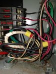
Well, that's what I was trying too avoid ? The picture a few above of small breaker box... there are 3 outlets on the bottom. Left one goes to pool lights (switch by pool), middle one goes to low voltage transformer (deck lights), right one goes to timer box. The bottom breaker (blk wire) goes to other box, connects to red wire that comes back and ties to wires going into left and middle outs. I checked the connection in the timer box, and it's got 120v. I was not wanting to pull all all those wires out, since lighting was fine before I started messing in the timer box. I haven't touched the breaker box.
 
To get GFCI protection for the lights the 120V runs from the small CB panel to the timer box to the LINE side fo the GFCI. Then the power for the lights should come from the LOAD side of the GCFI. Usually the LINE side is the top connections and the LOAD side is the bottom connections if the GFCI is properly oriented.

Both the light hot wire and neutral wire need to be connected to the LOAD side of the GFCI.

That extra red and white wires is carrying the power back from the LOAD side of the GFCI into the CB box to connect to the lights. The zero red wire should be getting power from the LOAD side of the GFCI for your light.

Is that outlet dead? If so that is why your lights are dead. Make sure that GFCI outlet is not tripped.

Go follow those wires.
 
Last edited:

Enjoying this content?

Support TFP with a donation.

Give Support
To get GFCI protection for the lights the 120V runs from the small CB panel to the timer box to the LINE side fo the GFCI. Then the power for the lights should come from the LOAD side of the GCFI. Usually the LINE side is the top connections and the LOAD side is the bottom connections if the GFCI is properly oriented.

Both the light hot wire and neutral wire need to be connected to the LOAD side of the GFCI.

That extra red and white wires is carrying the power back from the LOAD side of the GFCI into the CB box to connect to the lights. The zero red wire should be getting power from the LOAD side of the GFCI for your light.

Is that outlet dead? If so that is why your lights are dead. Make sure that GFCI outlet is not tripped.

Go follow those wires.
F@ck, didn't even think about the outlet being GFCI. No power to it and won't reset. That's what's wired wrong. One more time....

Edit: all set! Line was on the bottom, so took 2 tries (couldn't read the back of the GFCI). Everything working! Thanks so much!
 
Last edited:
  • Like
Reactions: ajw22
Thread Status
Hello , This thread has been inactive for over 60 days. New postings here are unlikely to be seen or responded to by other members. For better visibility, consider Starting A New Thread.