Hi all,
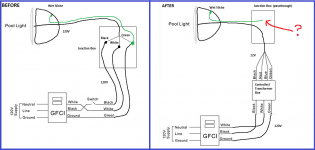
I replaced my 120v lighting with a Poolexa lighting system. It's a Controller/Transformer combo which is fed 120V from GFCI and outputs 12v to the light. The light is mounted to a metal niche. The light cable runs through the old junction box, through the old conduit, and eventually comes out of the conduit and into the breaker box. Finally that 12v cable is fed to the controller/transformer. All of this is straightforward and makes sense.
What is confusing the heck out of me is what to do with the ground cable coming into the junction box from inside the wet niche (highlighted in red in the diagram).
I have attached a before/after diagram showing everything in detail. Any help is appreciated!