Troubleshooting blower (AFS light)

Mar 22, 2024
8
San Diego
Hi, new here, and trying to avoid replacing my entire heater. I have a Pentair Mastertemp 400 (somewhere between 7 and 14 years old; I can't find the paperwork from the previous owner) that stopped heating b/c of an AFS light. I verified that the airflow sensor still works by blowing into the blower intake with a leaf blower (causing the light to go off). Also, the blower was obviously spinning freely. I also took off the blower shroud to verify that the blower is clear of debris and obstructions, and it's very easy to turn (and keeps turning when I stop blowing or pushing it, meaning the bearing seems fine).

However, when I start the heating cycle, the relay clicks and the blower moves ever so slightly (maybe a half inch) and stops, and the AFS light comes on.

Separately, bypassing the switch with a jumper wire hasn't worked. I'm pretty deep in troubleshooting...yesterday I was temporarily able to get the blower to come on by bypassing both the pressure switch (turns out it wasn't set correctly) and the AFS, but it made a weird deep pulsing noise while it was producing heat. I haven't been able to replicate that.

The igniter is reading 88 Ohms, and the circuit board appears to be fine based on other troubleshooting tips I've read around the web. My pump is good to go (although my salt has been too high for a while). My main filter was recently cleaned.

To narrow down my question, any idea what is keeping my blower from turning back on? Thanks in advance...I'd love to avoid a $4500 heater replacement!
 
Welcome to TFP.

Below is the wiring diagram for the MasterTemp heater.

Do you have a multimeter and know how to check voltage and continuity?

The blower is the first thing that should turn on when the heater starts up. The FENWAL module controls the blower power through a relay that connects F1 to F2. Before powering up the blower the FENWAL checks that the AFS is OPEN.

Have you checked the continuity of the AFS that it is OPEN when no air is blown into it and closes when air is blown into it? You should not blow in more air then you can blow out of your mouth or you may break the switch. The leaf blower is too much.

If the AFS is opening and closing properly then check if you get voltage at F2 when the heater starts up. If you do not have voltage at F2 and have voltage at F1 then the FENWAL may be bad. The F1/F2 contacts on the Fenwal are supposed to close and start the blower motor when you have 24 volts between "TH" and the 24 volt ground. If you have 24 volts at these 2 points and the contacts do not close, you would need to replace the Fenwal.

If you have voltage at F2 and the blower does not run then you may have a problem with the blower motor.

You can read more about the AFS and blower at Pentair MasterTemp Heaters - Further Reading

Do those checks and report what you find.

This thread may be of help...


full
 
Last edited:
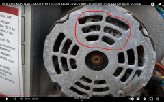
I had a problem with my pentair natrual gas mastertemp 400, the blower motor would turn on backwards or not spin at all and the "need maintenance" light would come on. Everything I read online said to replace the blower for 300$. I talked to an electrical engineer and ended up removing the back cover of the blowers electric motor and replacing the start capacitor for $16. Worked like a charm. I could not find a 120v capacitor but you can use a higher voltage capacitor as long as all the other parameters are the same.
 
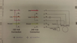
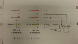
The blower has 3 sets of windings.

2 main run windings and an auxiliary start winding.

Red and blue go to one set of windings.

Black and yellow go to the other set.

For 120 volts, the windings are in parallel.

For 240 volts, the windings are in series.

The auxiliary start winding is in parallel with the black --> yellow winding.

Remove the capacitor and test for resistance from red to blue and black to yellow. The values should be the same.

Label the capacitor wires C1 and C2. Test from C1 to C2, C1 to black, C1 to yellow and C1 to white.

Test from C2 to black, C2 to yellow and C2 to white.

Test from each wire to the green ground wire to see if any wires are shorted to ground.

1711126223783.png

 
The blower has 3 sets of windings.

2 main run windings and an auxiliary start winding.

Red and blue go to one set of windings.

Black and yellow go to the other set.

For 120 volts, the windings are in parallel.

For 240 volts, the windings are in series.

The auxiliary start winding is in parallel with the black --> yellow winding.

Remove the capacitor and test for resistance from red to blue and black to yellow. The values should be the same.

Label the capacitor wires C1 and C2. Test from C1 to C2, C1 to black, C1 to yellow and C1 to white.

Test from C2 to black, C2 to yellow and C2 to white.

Test from each wire to the green ground wire to see if any wires are shorted to ground.

View attachment 560050Screenshot 2024-03-23 at 11.30.50 AM.png

First of all, thank you all for the detailed responses.

How do I remove the capacitor? The cover doesn't have any screws (besides the grounding screw), and those four metal clips are holding it on. I haven't tested a capacitor before...I do know how to use a multimeter but I'm not an expert. I'll try to follow the directions you folks posted.

Thanks again!
 
Welcome to TFP.

Below is the wiring diagram for the MasterTemp heater.

Do you have a multimeter and know how to check voltage and continuity?

The blower is the first thing that should turn on when the heater starts up. The FENWAL module controls the blower power through a relay that connects F1 to F2. Before powering up the blower the FENWAL checks that the AFS is OPEN.

Have you checked the continuity of the AFS that it is OPEN when no air is blown into it and closes when air is blown into it? You should not blow in more air then you can blow out of your mouth or you may break the switch. The leaf blower is too much.

If the AFS is opening and closing properly then check if you get voltage at F2 when the heater starts up. If you do not have voltage at F2 and have voltage at F1 then the FENWAL may be bad. The F1/F2 contacts on the Fenwal are supposed to close and start the blower motor when you have 24 volts between "TH" and the 24 volt ground. If you have 24 volts at these 2 points and the contacts do not close, you would need to replace the Fenwal.

If you have voltage at F2 and the blower does not run then you may have a problem with the blower motor.

You can read more about the AFS and blower at Pentair MasterTemp Heaters - Further Reading

Do those checks and report what you find.

This thread may be of help...


full
I was able to confirm that F2 gets 120V when the heater starts up. Also the AFS still works based on open when static and fully closed when I lightly blew into it.

Testing TH to the GND terminal 3 to the right of it I got, oddly, 2.4V whenever the heater had power (just circuit breaker on), and that didn’t changed once I turned it on.

What do you think? Thanks again.
 

Enjoying this content?

Support TFP with a donation.

Give Support
Maybe take the motor to a local electric motor shop to see if they can check it out for you.

Can you show a video of what is happening?
I'll take one tomorrow when the sun is up if I can. But basically, the relay clicks, it starts to move for a split second and then stops, after which I get the AFS light. There is nothing impeding its movement, it moves freely by hand (bearing feels good to go).
 
  • Like
Reactions: JamesW
Remove the capacitor and test for resistance from red to blue and black to yellow. The values should be the same.

Label the capacitor wires C1 and C2. Test from C1 to C2, C1 to black, C1 to yellow and C1 to white.

Test from C2 to black, C2 to yellow and C2 to white.

Test from each wire to the green ground wire to see if any wires are shorted to ground.

View attachment 560050

IMG_2663.jpeg
The blower has 3 sets of windings.

2 main run windings and an auxiliary start winding.

Red and blue go to one set of windings.

Black and yellow go to the other set.

For 120 volts, the windings are in parallel.

For 240 volts, the windings are in series.

The auxiliary start winding is in parallel with the black --> yellow winding.

Remove the capacitor and test for resistance from red to blue and black to yellow. The values should be the same.

Label the capacitor wires C1 and C2. Test from C1 to C2, C1 to black, C1 to yellow and C1 to white.

Test from C2 to black, C2 to yellow and C2 to white.

Test from each wire to the green ground wire to see if any wires are shorted to ground.

View attachment 560050


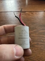
I don’t understand how to check the capacitor windings, bc I only have the red and black wire. I’m replacing it just in case since it’s cheap, but what am I missing here?IMG_2663.jpeg
 
Test the capacitor using a meter that can test for capacitance or just replace the capacitor.

Test the start windings using a meter set to resistance in ohms with all power turned off.
 
Can you clarify how to test the windings?

I made some more progress. I swapped out the capacitor; it's larger than the old one, but it's the same uF and voltage rating (8uF, 250V, 50/60Hz). No joy with the new capacitor.

However, I did test the voltage to the two wires when I powered on the control panel: 0.5V
and when the heater was turned on: 40V.

So I'm still stuck with an AFS light, a verified working AFS switch, and not sure how to get the motor to start turning. It was starting to turn and stopping before, but now it's not turning at all. Is the windings the next step? Trying to exhaust EVERYTHING before I buy a new heater, and I'm a little nervous about swapping out the blower motor ($500-700) on a very old heater, only to have to swap out the whole thing soon after.

Thanks again! I need the help! :geek:
 
1713971490175.png

The blower has 3 sets of windings.

2 main run windings and an auxiliary start winding.

Red and blue go to one set of windings.

Black and yellow go to the other set.

For 120 volts, the windings are in parallel.

For 240 volts, the windings are in series.

The auxiliary start winding is in parallel with the black --> yellow winding.

Remove the capacitor and test for resistance from red to blue and black to yellow. The values should be the same.

Label the capacitor wires C1 and C2. Test from C1 to C2, C1 to black, C1 to yellow and C1 to white.

Test from C2 to black, C2 to yellow and C2 to white.

Test from each wire to the green ground wire to see if any wires are shorted to ground.
 
Testing the Air Blower.

The blower has 3 sets of windings.

2 main run windings and an auxiliary start winding.

Red and blue go to one set of windings.

Black and yellow go to the other set.

For 120 volts, the windings are in parallel.
For 240 volts, the windings are in series.
The auxiliary start winding is in parallel with the black --> yellow winding.

Remove the capacitor and test for resistance from red to blue and black to yellow. The values should be the same.

Label the capacitor wires C1 and C2.
Test from C1 to C2, C1 to black, C1 to yellow and C1 to white.
Test from C2 to black, C2 to yellow and C2 to white.
Test from each wire to the green ground wire to see if any wires are shorted to ground.

Check the power going to the blower:

When the heater tries to start, you should be seeing 240 volts from red to black on the wires going to the blower.

You can disconnect the blower plug and test the power at the red and black wires.

Have the meter connected because the power might shut off after a few seconds.

The red should be powered any time the heater is powered.

So, you should get 120 volts on that leg before the heater tries to start.

The black wire doesn't get power until the blower is supposed to be on.

When the heater tries to start, power is applied to black and you should get 240 from red to black.

Note: No guarantees on anything.

Only do what you know that you can do safely.

Do at your own risk.


To test the motor directly wire as follows:

For 240 volts, Black to hot leg, Red to the other hot leg, blue and yellow connected together.

The white wire is connected to the black wire, so cap it off when applying power to the black wire so that it doesn't make contact with anything.

For 120 volts, red and yellow to one line, black to the other line and blue and white connected together.

If the power test shows that the motor is good, the problem is likely to be with the ignition control module or the main board.

Note: the above is believed to be correct. It's presented as is. If you want to test like this, you do it at your own risk.

Do the resistance test first as that should tell you something.

Test the capacitance of the capacitor to make sure that it's correct.

One power leg is always connected to the blower motor and the black wire from F2 is the switched leg.
 
Ok, I got some readings for the wire harness coming from the blower:

Y W: 11.6 Ohm
Y BK: 11.6
W BK: 0.1
All other combos were open, including R/Bl and G/W

C1 Bk: 11.6
C1 Y: 0
C1 W: 11.6
C1 C2: open
C2 Bk: open
C2 Y: open
C2 W: open

Across new capacitor: open

Also checked all values with capacitor bypassed (wires connected) and got the same results.

To ground wire that connects to blower housing:

Y: open
G: 0
W: open
Bk: open
Bl: 4.4 KOhm
  • Bl to G in the connector to the windings also gives various readings around .5 MOhm
R: open

Also, it’s possible I’m not getting great readings as the Multimeter probes aren’t a perfect fit for the harness. I could be doing something wrong.

========

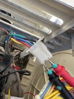
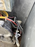
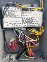
Separately, I’m not sure which blower plug you mean to test the 240V hot wires. I’ve attached a couple pics of what I’m looking at, plus one of how I was getting readings:

IMG_2726.jpegIMG_2727.jpegIMG_2728.jpeg