Sunday project: replacing my old intermatic timer that controls the SWG with a sonoff R2 so I can do it from my phone and have a better control over the schedule (I'm also in the process of researching ripping it all out and going to a nixie standalone, but this is step one because the R2 is easy to come by and the raspberry pi is not).
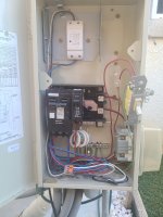
it seems the pump is also wired in with the intermatic timer. I think I know how to wire the R2 for just the SWG on and off, but how do I handle the extra pump wiring here?


it seems the pump is also wired in with the intermatic timer. I think I know how to wire the R2 for just the SWG on and off, but how do I handle the extra pump wiring here?
Last edited: